CONNECTING DEVICES
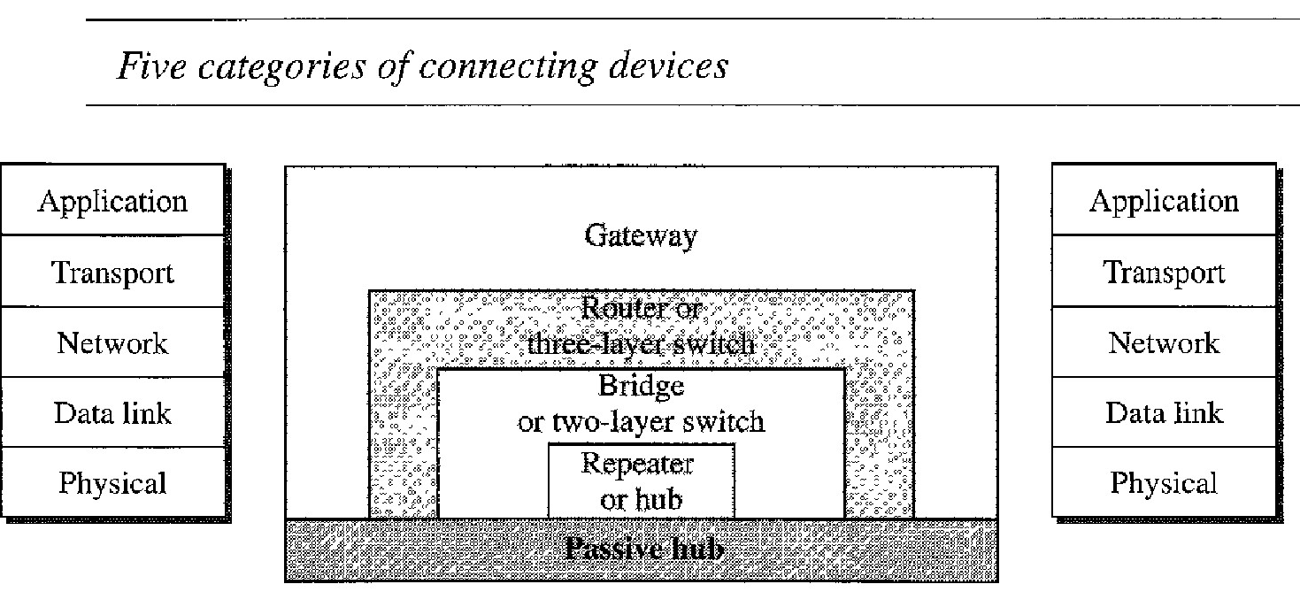
The five categories based on the layer in which connecting devices operate in a network can be defined as
Those which operate below the physical layer such as a passive hub.
Those which operate at the physical layer (a repeater or an active hub).
Those which operate at the physical and data link layers (a bridge or a two-layer switch).
Those which operate at the physical, data link, and network layers (a router or a three-layer switch).
hose which can operate at all five layers (a gateway).
A passive hub is just a connector. It connects the wires coming from different branches. In a star-topology Ethernet LAN, a passive hub is just a point where the signals coming from different stations collide; the hub is the collision point. This type of a hub is part of the media; its location in the Internet model is below the physical layer.
A repeater is a device that operates only in the physical layer. Signals that carry information within a network can travel a fixed distance before attenuation endangers the integrity of the data. A repeater receives a signal and, before it becomes too weak or corrupted, regenerates the original bit pattern. The repeater then sends the refreshed signal. A repeater can extend the physical length of a LAN. A repeater does not actually connect two LANs; it connects two segments of the same LAN. The segments connected are still part of one single LAN. A repeater is not a device that can connect two LANs of different protocols.
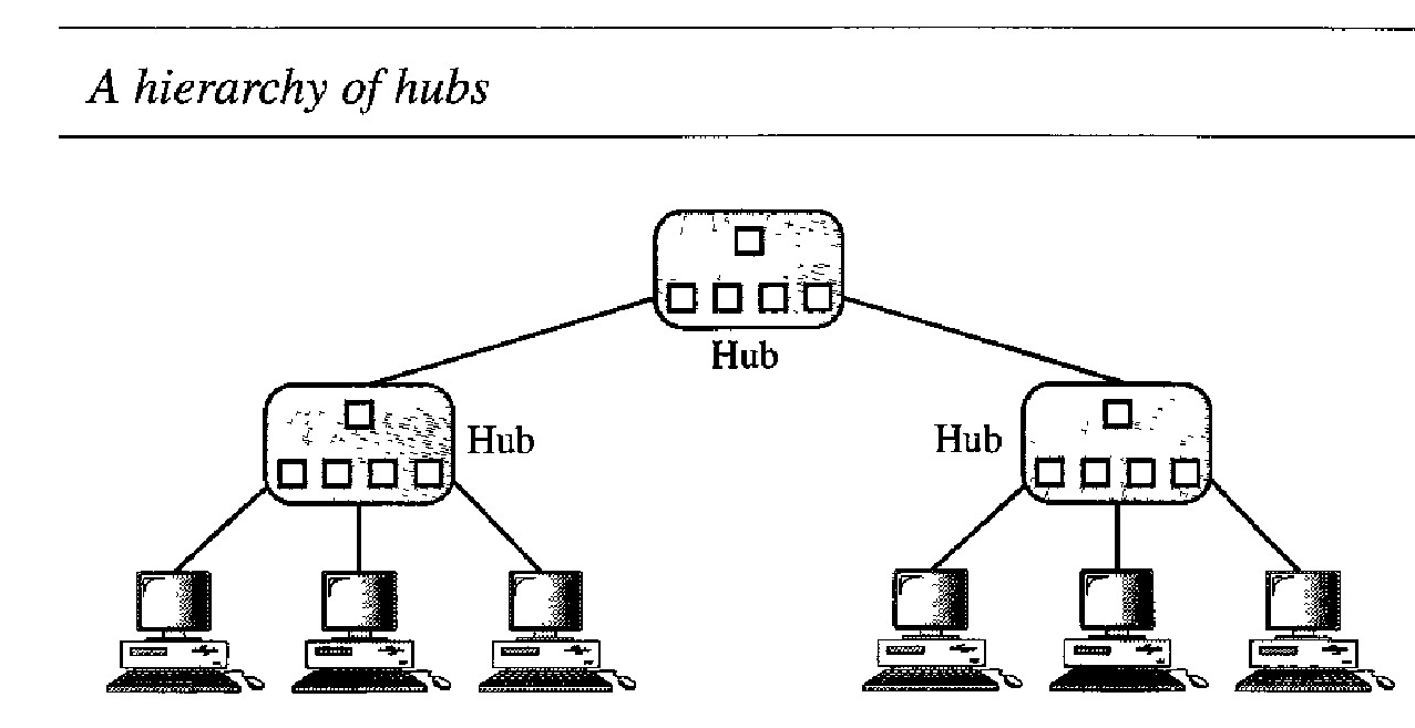
An active hub is actually a multiport repeater. It is normally used to create connections between stations in a physical star topology. We have seen examples of hubs in some Ethernet implementations (10 Base- T, for example).
A bridge operates in both the physical and the data link layer. As a physical layer device, it regenerates the signal it receives. As a data link layer device, the bridge can check the physical (MAC) addresses (source and destination) contained in the frame.
A bridge has filtering capability. It can check the destination address of a frame and decide if the frame should be forwarded or dropped. If the frame is to be forwarded, the decision must specify the port. A bridge has a table that maps addresses to ports.
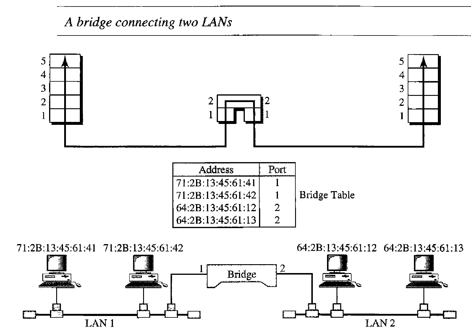
Q. A bridge has a table used in filtering decisions. Demonstrate this ?
Two LANs are connected by a bridge. If a frame destined for station 712B13456142 arrives at port 1, the bridge consults its table to find the departing port. According to its table, frames for 7l2B13456142 leave through port 1; therefore, there is no need for forwarding, and the frame is dropped.
On the other hand, if a frame for 712B13456141 arrives at port 2, the departing port is port 1 and the frame is forwarded. In the first case, LAN 2 remains free of traffic; in the second case, both LANs have traffic. In our example, we show a two-port bridge; in reality a bridge usually has more ports.
Note also that a bridge does not change the physical addresses contained in the frame.
Explain Transparent bridges and their Working ?
A transparent bridge is a bridge in which the stations are completely unaware of the bridge's existence. If a bridge is added or deleted from the system, reconfiguration of the stations is unnecessary.
Frames must be forwarded from one station to another.
The forwarding table is automatically made by learning frame movements in the network
Loops in the system must be prevented.
The earliest bridges had forwarding tables that were static. The systems administrator would manually enter each table entry during bridge setup. Although the process was simple, it was not practical. If a station was added or deleted, the table had to be modified manually. The same was true if a station's MAC address changed, which is not a rare event. For example, putting in a new network card means a new MAC address.
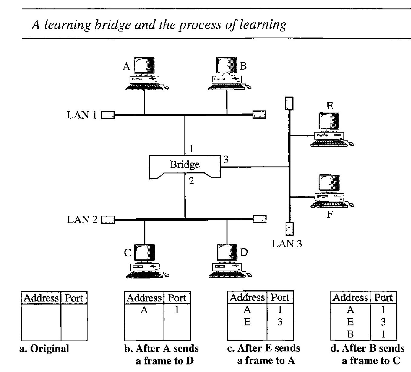
To make a table dynamic, we need a bridge that gradually learns from the frame movements. This process is illustrated by :
When station A sends a frame to station D, the bridge does not have an entry for either D or A. The frame goes out from all three ports; the frame floods the network. However, by looking at the source address, the bridge learns that station A must be located on the LAN connected to port 1. This means that frames destined for A, in the future, must be sent out through port 1. The bridge adds this entry to its table. The table has its first entry now
When station E sends a frame to station A, the bridge has an entry for A, so it for- wards the frame only to port 1. There is no flooding. In addition, it uses the source address of the frame, E, to add a second entry to the table.
When station B sends a frame to C, the bridge has no entry for C, so once again it floods the network and adds one more entry to the table.
The process of learning continues as the bridge forwards frames.
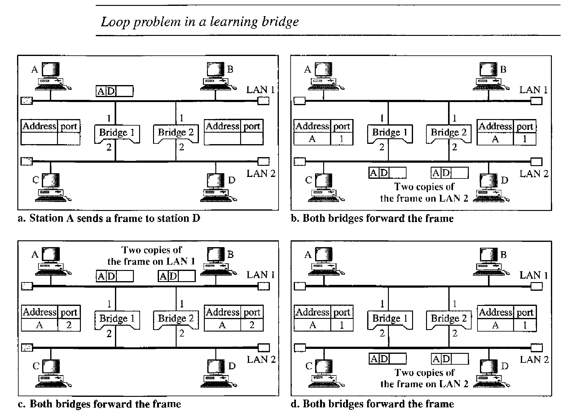
Loop Problem in Transparent bridges
Transparent bridges work fine as long as there are no redundant bridges in the system. Systems administrators, however, like to have redundant bridges (more than one bridge between a pair of LANs) to make the system more reliable.
If a bridge fails, another bridge takes over until the failed one is repaired or replaced. Redundancy can create loops in the system, which is very undesirable.
Station A sends a frame to station D. The tables of both bridges are empty. Both forward the frame and update their tables based on the source address A.
Now there are two copies of the frame on LAN 2. The copy sent out by bridge 1 is received by bridge 2, which does not have any information about the destination address D; it floods the bridge. The copy sent out by bridge 2 is received by bridge 1 and is sent out for lack of information about D.
Now there are two copies of the frame on LAN 1. Step 2 is repeated, and both copies flood the network.
The process continues on and on. Note that bridges are also repeaters and regenerate frames. So in each iteration, there are newly generated fresh copies of the frames.
To solve the looping problem, the IEEE specification requires that bridges use the spanning tree algorithm to create a loopless topology.