Spanning Tree
In a bridged LAN, a spanning tree means creating a topology in which each LAN can be reached from any other LAN through one path only (no loop).
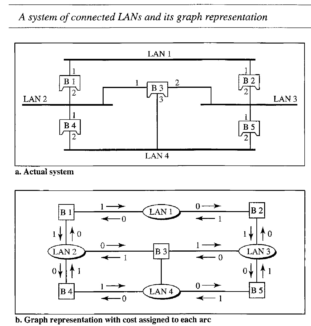
We cannot change the physical topology of the system because of physical connections between cables and bridges, but we can create a logical topology that overlays the physical one
We have shown both LANs and bridges as nodes and the connecting arcs show the connection of a LAN to a bridge and vice versa.
To find the spanning tree, we need to assign a cost (metric) to each arc. The interpretation of the cost is left up to the systems administrator. It may be the path with minimum hops (nodes), the path with minimum delay, or the path with maximum bandwidth. If two ports have the same shortest value, the systems administrator just chooses one. Here we have chosen the minimum hops. However the hop count is normally 1 from a bridge to the LAN and 0 in the reverse direction.
The process to find the spanning tree involves three steps:
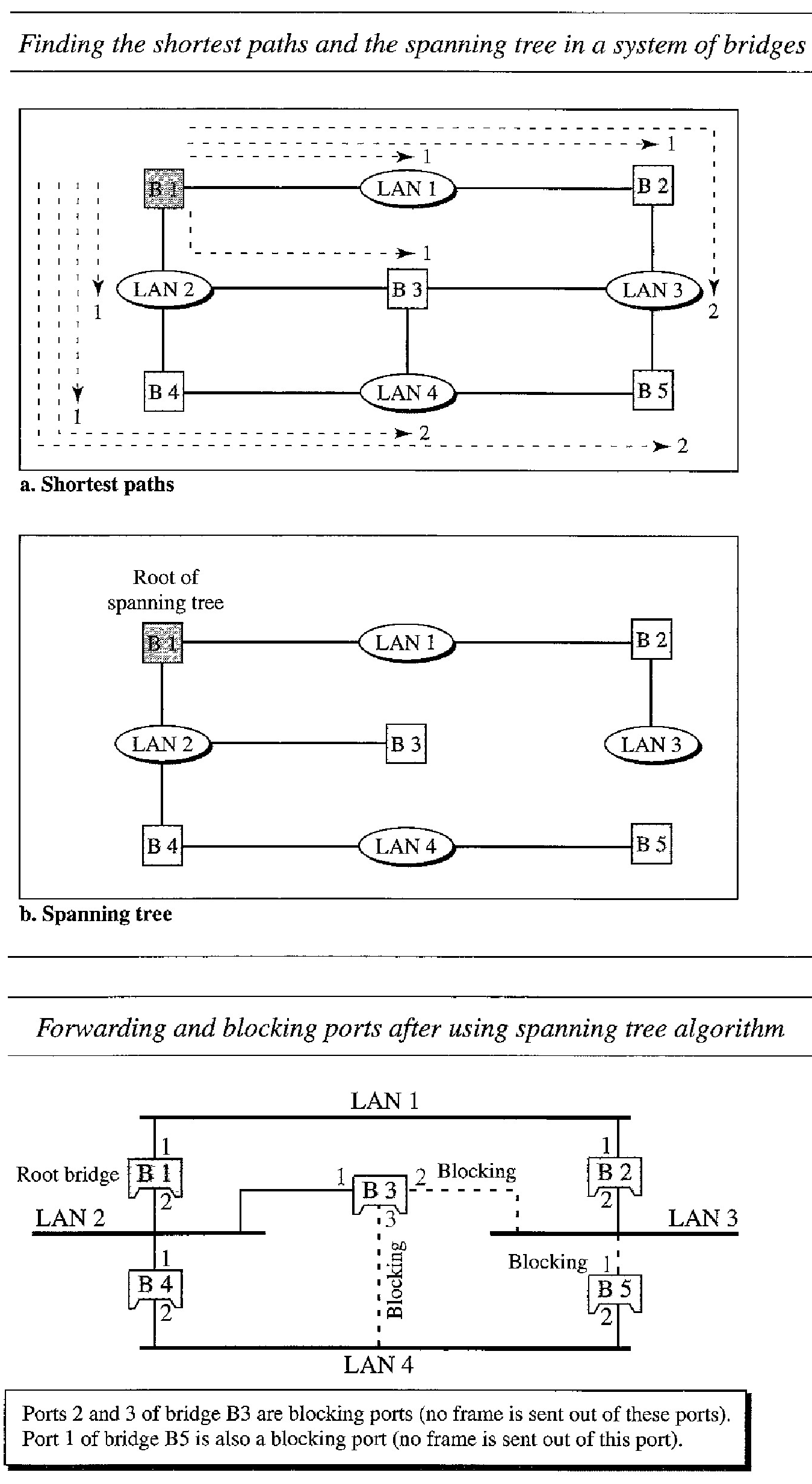
Every bridge has a built-in ID (normally the serial number, which is unique). Each bridge broadcasts this ID so that all bridges know which one has the smallest ID. The bridge with the smallest ID is selected as the root bridge (root of the tree). We assume that bridge B 1 has the smallest ID. It is, therefore, selected as the root bridge.
The algorithm tries to find the shortest path (a path with the shortest cost) from the root bridge to every other bridge or LAN. The shortest path can be found by examining the total cost from the root bridge to the destination
Based on the spanning tree. we mark the ports that are part of the spanning tree, the forwarding ports, which forward a frame that the bridge receives. We also mark those ports that are not part of the spanning tree, the blocking ports, which block the frames received by the bridge.
Source Routing Bridges
Another way to prevent loops in a system with redundant bridges is to use source routing bridges. A transparent bridge's duties include filtering frames, forwarding, and blocking. In a system that has source routing bridges, these duties are performed by the source station and, to some extent, the destination station.
In source routing, a sending station defines the bridges that the frame must visit. The addresses of these bridges are included in the frame. In other words, the frame con- tains not only the source and destination addresses, but also the addresses of all bridges to be visited.
The source gets these bridge addresses through the exchange of special frames with the destination prior to sending the data frame.
Source routing bridges were designed by IEEE to be used with Token Ring LANs. These LANs are not very common today.
Two-Layer Switches
A three-layer switch is used at the network layer; it is a kind of router. The two-layer switch performs at the physical and data link layers.
A two-layer switch is a bridge, a bridge with many ports and a design that allows better (faster) performance. A bridge with a few ports can connect a few LANs together. A bridge with many ports may be able to allocate a unique port to each station, with each station on its own independent entity. This means no competing traffic (no collision, as we saw in Ethernet).
A two-layer switch, as a bridge does, makes a filtering decision based on the MAC address of the frame it received. However, a two-layer switch can be more sophisti- cated. It can have a buffer to hold the frames for processing. It can have a switching factor that forwards the frames faster. Some new two-layer switches, called cut-through switches, have been designed to forward the frame as soon as they check the MAC addresses in the header of the frame.
Routers
A router is a three-layer device that routes packets based on their logical addresses (host-to-host addressing).
A router normally connects LANs and WANs in the Internet and has a routing table that is used for making decisions about the route. The routing tables are normally dynamic and are updated using routing protocols.
Three- Layer Switches : A three-layer switch is a router, but a faster and more sophisticated. The switching fabric in a three-layer switch allows faster table lookup and forwarding.
A gateway : is normally a computer that operates in all five layers of the Internet or seven layers of OSI model. A gateway takes an application message, reads it, and interprets it. This means that it can be used as a connecting device between two internetworks that use different models. For example, a network designed to use the OSI model can be connected to another network using the Internet model. The gateway connecting the two systems can take a frame as it arrives from the first system, move it up to the OSI application layer, and remove the message. Gateways can provide security as it can be used to filter unwanted application-layer messages.
Network Layer
The network layer is responsible for the source-to-destination delivery of a packet, possibly across multiple networks (links). Whereas the data link layer oversees the delivery of the packet between two systems on the same network (links), the network layer ensures that each packet gets from its point of origin to its final destination.
The network layer adds a header that includes the logical addresses of the sender and receiver to the packet coming from the upper layer. If a packet travels through the Internet, we need this addressing system to help distinguish the source and destination.
When independent networks or links are connected together to create an internetwork, routers or switches route packets to their final destination. One of the functions of the network layer is to provide a routing mechanism.
For this level of communication, we need a global addressing scheme; we called this logical addressing IP address to mean a logical address in the network layer of the TCP/IP protocol suite.
The Internet addresses are 32 bits in length; this gives us a maximum of 232 addresses. The need for more addresses, in addition to other concerns about the IP layer, motivated a new design of the IP layer called the new generation of IP or IPv6. In this version, the Internet uses 128-bit addresses that give much greater flexibility in address allocation. These addresses are referred to as IPv6 (IP version 6) addresses.
An IPv4 address is a 32-bit address that uniquely and universally defines the connection of a device (for example, a computer or a router) to the Internet.
Address Space
A protocol such as IPv4 that defines addresses has an address space. An address space is the total number of addresses used by the protocol. If a protocol uses N bits to define an address, the address space is 2N because each bit can have two different values (0 or 1) and N bits can have 2N values.
There are two prevalent notations to show an IPv4 address: binary notation and dotteddecimal notation.
Binary Notation : In binary notation, the IPv4 address is displayed as 32 bits. Each octet is often referred to as a byte. So it is common to hear an IPv4 address referred to as a 32-bit address or a 4-byte address. The following is an example of an IPv4 address in binary notation:01110101 10010101 00011101 00000010
Dotted-Decimal Notation : To make the IPv4 address more compact and easier to read, Internet addresses are usually written in decimal form with a decimal point (dot) separating the bytes. The following is the dotted-decimal notation of the above address: 117.149.29.2
Q. Change the following IPv4 addresses from binary notation to dotted-decimal notation.
10000001 00001011 00001011 11101111
11000001 10000011 00011011 11111111
We replace each group of 8 bits with its equivalent decimal number and add dots for separation.
129.11.11.239 and 193.131.27.255
Q. Find the error, if any, in the following IPv4 addresses.
a. 111.56.045.78 : There must be no leading zero (045).
b. 221.34.7.8.20 : There can be no more than four numbers in an IPv4 address.
c. 75.45.301.14 : Each number needs to be less than or equal to 255 (301 is outside this range).
d. 11100010.23.14.67 : A mixture of binary notation and dotted-decimal notation is not allowed.
Classful Addressing
IPv4 addressing, at its inception, used the concept of classes. This architecture is called classful addressing. In classful addressing, the address space is divided into five classes: A, B, C, D, and E. Each class occupies some part of the address space.
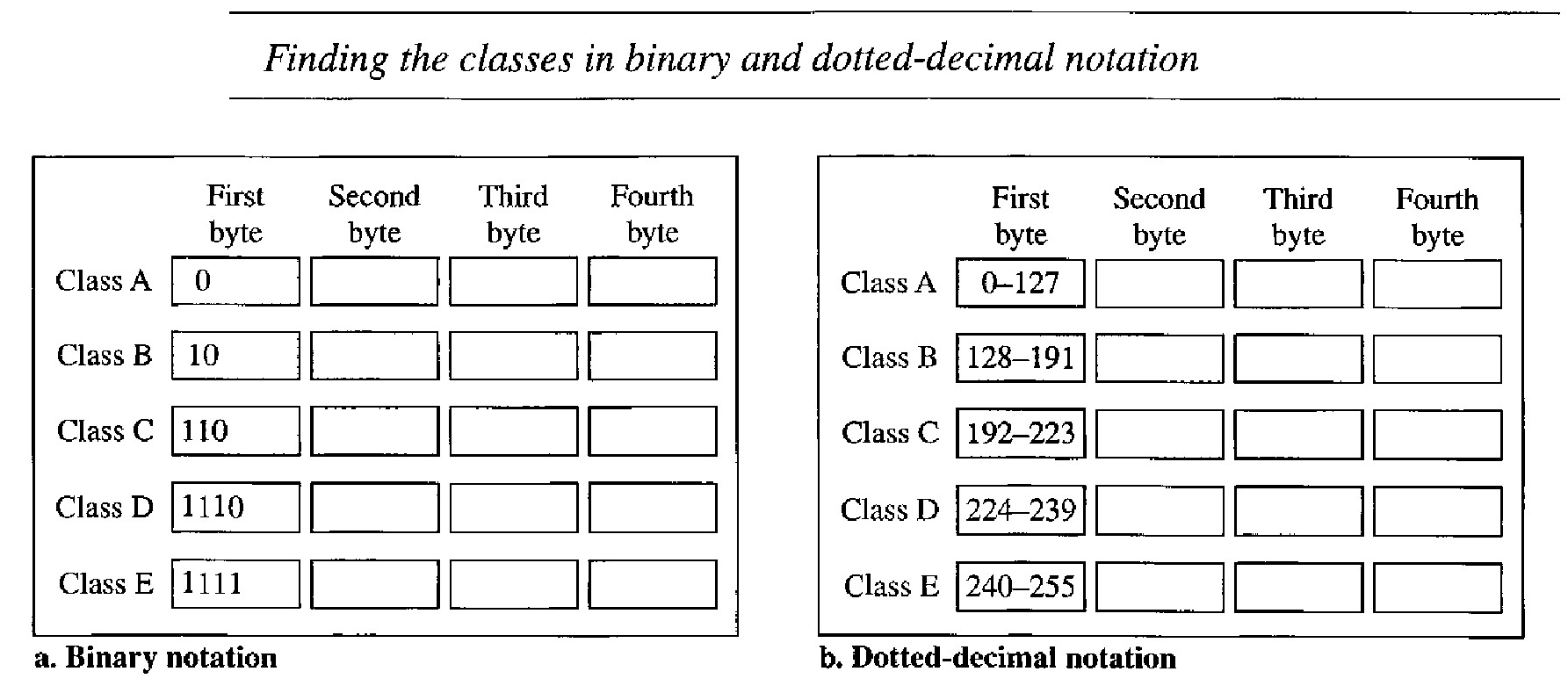
If the address is given in binary notation, the first few bits can immediately tell us the class of the address. If the address is given in decimal-dotted notation, the first byte defines the class.
Example :00000001 00001011 00001011 1110 1111. The first bit is O.This is a class A address.
Example :11000001 10000011 00011011 11111111. The first 2 bits are 1; the third bit is O. This is a class C address.
Example :14.23.120.8 The first byte is 14 (between 0 and 127); the class is A.
Example :252.5.15.111. The first byte is 252 (between 240 and 255); the class is E.
Classes and Blocks
One problem with classful addressing is that each class is divided into a fixed number of blocks with each block having a fixed size as shown
Class A addresses were designed for large organizations with a large number of attached hosts or routers. Class B addresses were designed for midsize organizations with tens of thousands of attached hosts or routers. Class C addresses were designed for small organizations with a small number of attached hosts or routers.
A block in class A address is too large for almost any organization. This means most of the addresses in class A were wasted and were not used. A block in class B is also very large, probably too large for many of the organizations that received a class B block. A block in class C is probably too small for many organizations.
Class D addresses were designed for multicasting, each address in this class is used to define one group of hosts on the Internet. The Internet authorities wrongly predicted a need for 268,435,456 groups. This never happened and many addresses were wasted here too. And lastly, the class E addresses were reserved for future use; only a few were used, resulting in another waste of addresses.
| Class | Number of blocks | Blocksize | Applications |
|---|---|---|---|
| A | 128 | 16777216 | UNICAST |
| B | 16384 | 65536 | UNICAST |
| C | 2097152 | 256 | UNICAST |
| D | 1 | 268435456 | MULTICAST |
| E | 1 | 268435456 | RESERVED |
Netid and Hostid
In classful addressing, an IP address in class A, B, or C is divided into netid and hostid. These parts are of varying lengths, depending on the class of the address.
In class A, one byte defines the netid and three bytes define the hostid. In class B, two bytes define the netid and two bytes define the hostid. In class C, three bytes define the netid and one byte defines the hostid
Although the length of the netid and hostid (in bits) is predetermined in c1assful addressing, we can also use a mask (also called the default mask), a 32-bit number made of contiguous 1's followed by contiguous O's.
The mask can help us to find the netid and the hostid. For example, the mask for a class A address has eight 1s, which means the first 8 bits of any address in class A define the netid; the next 24 bits define the hostid.
The last column shows the mask in the form /n where 'n' can be 8, 16, or 24 in classful addressing. This notation is also called slash notation or Classless Interdomain Routing (CIDR) notation.
| Class | Binary | Dotted decimal | CIDR |
|---|---|---|---|
| A | 11111111 00000000 00000000 00000000 | 255.0.0.0 | /8 |
| B | 11111111 11111111 00000000 00000000 | 255.255.0.0 | /16 |
| C | 11111111 11111111 11111111 00000000 | 255.255.255.0 | /24 |
Subnetting
If an organization was granted a large block in class A or B, it cou1d divide the addresses into several contiguous groups and assign each group to smaller networks (called subnets) or, in rare cases, share part of the addresses with neighbors.
Subnetting increases the number of 1's in the mask.
Supernetting
The time came when most of the class A and class B addresses were depleted; however, there was still a huge demand for midsize blocks. The size of a class C block with a maximum number of 256 addresses did not satisfy the needs of most organizations
In supernetting, an organization can combine several class C blocks to create a larger range of addresses. In other words, several networks are combined to create a supernetwork or a supernet.
An organization can apply for a set of class C blocks instead of just one. For example, an organization that needs 1000 addresses can be granted four contiguous class C blocks. The organization can then use these addresses to create one supernetwork.
Supernetting decreases the number of 1's in the mask. For example, if an organization is given four class C addresses, the mask changes from 124 to 122. Classless addressing eliminated the need for supernetting.
Address Depletion
The flaws in c1assful addressing scheme combined with the fast growth of the Internet led to the near depletion of the available addresses.
Yet the number of devices on the Internet is much less than the 232 address space. We have run out of class A and B addresses, and a class C block is too small for most midsize organizations. One solution that has alleviated the problem is the idea of classless addressing.
Classful addressing, which is almost obsolete, is replaced with classless addressing.