INTERNETWORKING
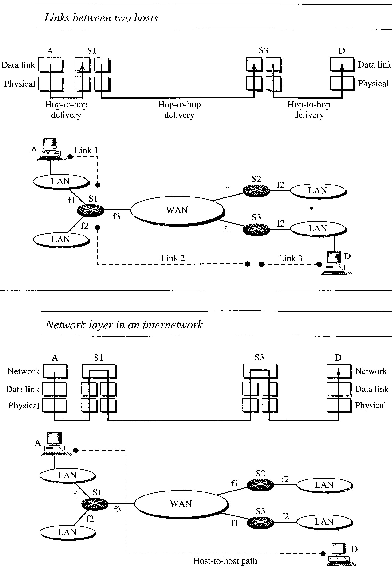
The physical and data link layers of a network operate locally. These two layers are jointly responsible for data delivery on the network from one node to the next
The above internetwork is made of five networks: four LANs and one WAN. If host A needs to send a data packet to host D, the packet needs to go first from A to RI (a switch or router), then from R1 to R3, and finally from R3 to host D. We say that the data packet passes through three links. In each link, two physical and two data link layers are involved.
However, When data arrive at interface f1 of R1, how does R1 know that interface f3 is the outgoing interface ? There is no provision in the data link (or physical) layer to help R1 make the right decision. The frame does not carry any routing information either. The frame contains the MAC address of A as the source and the MAC address of R1 as the destination. For a LAN or a WAN, delivery means carrying the frame through one link, and not beyond.
Need for Network Layer
To solve the problem of delivery through several links, the network layer (or the internetwork layer, as it is sometimes called) was designed. The network layer is responsible for host-to-host delivery and for routing the packets through the routers or switches.
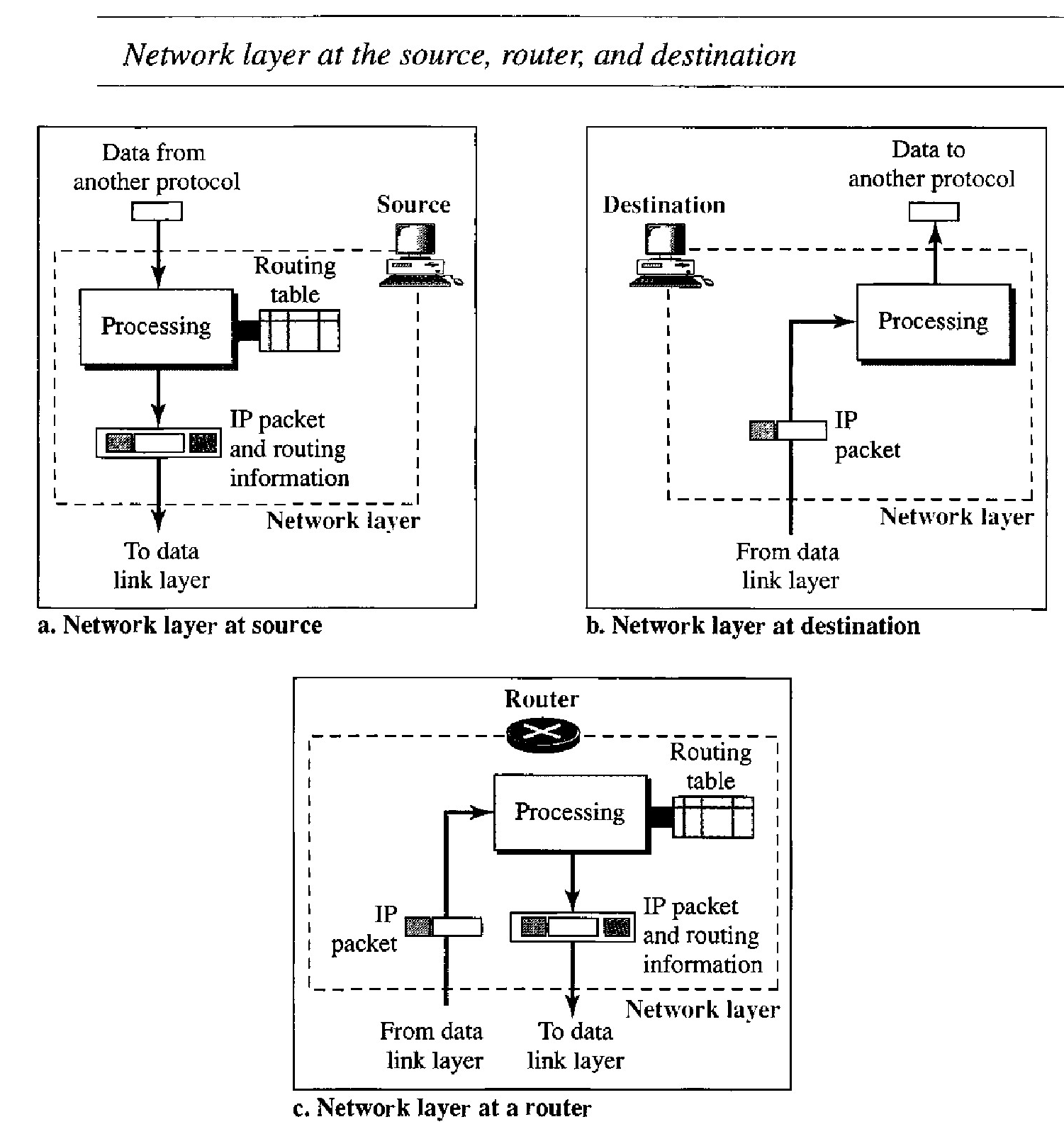
In above figure, The network layer at the source is responsible for creating a packet from the data coming from another protocol (such as a transport layer protocol or a routing protocol).
The header of the packet contains, among other information, the logical addresses of the source and destination. The network layer is responsible for checking its routing table to find the routing information (such as the outgoing interface of the packet or the physical address of the next node). If the packet is too large, the packet is fragmented.
The network layer at the switch or router is responsible for routing the packet. When a packet arrives, the router or switch consults its routing table and finds the inter- face from which the packet must be sent. The packet, after some changes in the header, with the routing information is passed to the data link layer again .
The network layer at the destination is responsible for address verification; it makes sure that the destination address on the packet is the same as the address of the host. If the packet is a fragment, the network layer waits until all fragments have arrived, and then reassembles them and delivers the reassembled packet to the transport layer.
The Internet, at the network layer, is a packet-switched network. Switching can be divided into three broad categories: circuit switching, packet switching, and message switching.
Packet switching uses either the virtual circuit approach or the datagram approach. The Internet has chosen the datagram approach to switching in the network layer. It uses the universal addresses defined in the network layer to route packets from the source to the destination.
Internet as a Connectionless Network
Delivery of a packet can be accomplished by using either a connection-oriented or a connectionless network service.
In a connection-oriented service, the source first makes a connection with the destination before sending a packet. When the connection is established, a sequence of packets from the same source to the same destination can be sent one after another. In this case, there is a relationship between packets. They are sent on the same path in sequential order. A packet is logically connected to the packet traveling before it and to the packet traveling after it. When all packets of a message have been delivered, the connection is terminated.
In a connection-oriented protocol, the decision about the route of a sequence of packets with the same source and destination addresses can be made only once, when the connection is established. Switches do not recalculate the route for each individual packet. This type of service is used in a virtual-circuit approach. to packet switching such as in Frame Relay and ATM.
In connectionless service, the network layer protocol treats each packet independently, with each packet having no relationship to any other packet. The packets in a message mayor may not travel the same path to their destination. This type of service is used in the datagram approach to packet switching. The Internet has chosen this type of service at the network layer.
The reason for this decision is that the Internet is made of so many heterogeneous networks that it is almost impossible to create a connection from the source to the destination without knowing the nature of the networks in advance.
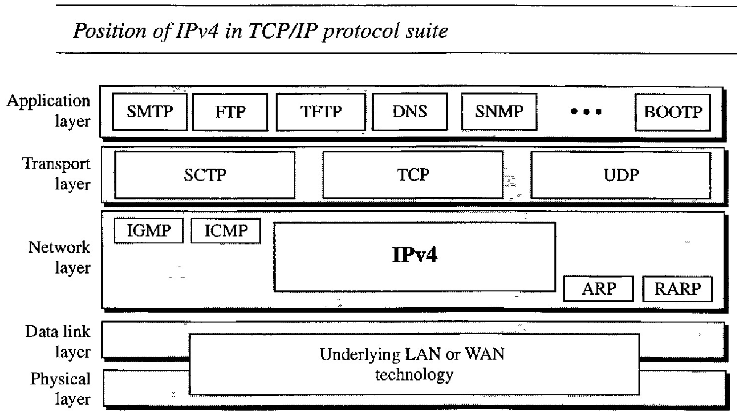
Internet Protocol version 4 (IPv4)
The Internet Protocol version 4 (IPv4) is the delivery mechanism used by the TCP/IP protocols.
IPv4 is an unreliable and connectionless datagram protocol-a best-effort delivery service. The term best-effort means that IPv4 provides no error control or flow control (except for error detection on the header). IPv4 assumes the unreliability of the underlying layers and does its best to get a transmission through to its destination, but with no guarantees.
IPv4 is also a connectionless protocol for a packet-switching network that uses the datagram approach. This means that each datagram is handled independently, and each datagram can follow a different route to the destination. This implies that data grams sent by the same source to the same destination could arrive out of order. Also, some could be lost or corrupted during transmission. Again, IPv4 relies on a higher-level protocol to take care of all these problems.
Packets in the IPv4 layer are called datagrams.
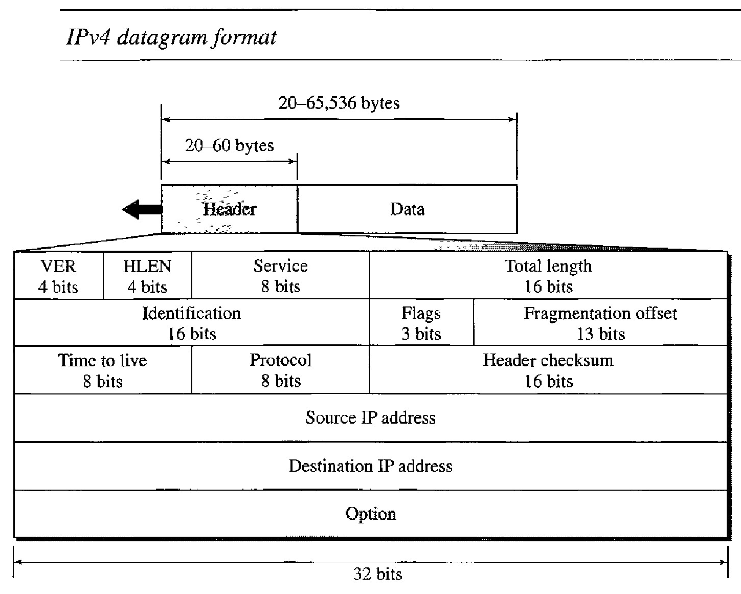
A datagram is a variable-length packet consisting of two parts: header and data. The header is 20 to 60 bytes in length and contains information essential to routing and delivery. It is customary in TCP/IP to show the header in 4-byte sections.
Description of the fields of datagrams are :
Version (VER) : This 4-bit field defines the version of the IPv4 protocol. Currently the version is 4. However, version 6 (or IPng) may totally replace version 4 in the future. If the machine is using some other version of IPv4, the datagram is discarded rather than interpreted incorrectly.
Header length (HLEN) : This 4-bit field defines the total length of the datagram header in 4-byte words. This field is needed because the length of the header is variable (between 20 and 60 bytes). When there are no options, the header length is 20 bytes, and the value of this field is 5 (5 x 4 = 20). When the option field is at its maximum size, the value of this field is 15 (15 x 4 = 60).
Total length : This is a 16-bit field that defines the total length (header plus data) of the IPv4 datagram in bytes. To find the length of the data coming from the upper layer, subtract the header length from the total length. The header length can be found by multiplying the value in the HLEN field by 4.
Length of data = total length - header length
Since the field length is 16 bits, the total length of the IPv4 datagram is limited to 65,535 (216 - 1) bytes, of which 20 to 60 bytes are the header and the rest is data from the upper layer.
Time to live :A datagram has a limited lifetime in its travel through an internet. This field is used mostly to control the maximum number of hops (routers) visited by the datagram. When a source host sends the datagram, it stores a number in this field. This value is approximately 2 times the maximum number of routes between any two hosts. Each router that processes the datagram decrements this number by 1. If this value, after being decremented, is zero, the router discards the datagram.
Source address : This 32-bit field defines the IPv4 address of the source. This field must remain unchanged during the time the IPv4 datagram travels from the source host to the destination host.
Destination address : This 32-bit field defines the IPv4 address of the destination. This field must remain unchanged during the time the IPv4 datagram travels from the source host to the destination host.
Q. An IPv4 packet has arrived with the first 8 bits as shown: 01000010 The receiver discards the packet. Why?
There is an error in this packet. The 4 leftmost bits (0100) show the version, which is correct. The next 4 bits (0010) show an invalid header length (2 x 4 = 8). The minimum number of bytes in the header must be 20. The packet has been corrupted in transmission.
Q. In an IPv4 packet, the value of HLEN is 1000 in binary. How many bytes of options are being carried by this packet?
The HLEN value is 8, which means the total number of bytes in the header is 8 x 4, or 32 bytes. The first 20 bytes are the base header, the next 12 bytes are the options.
Q. In an IPv4 packet, the value of HLEN is 5, and the value of the total length field is Ox0028. How many bytes of data are being carried by this packet?
The HLEN value is 5, which means the total number of bytes in the header is 5 x 4, or 20 bytes (no options). The total length is 40 bytes, which means the packet is carrying 20 bytes of data (40- 20).
Q. An IPv4 packet has arrived with the first few hexadecimal digits as shown. 0x45000028000100000102 ... How many hops can this packet travel before being dropped? The data belong to what upper-layer protocol?
To find the time-to-live field, we skip 8 bytes (16 hexadecimal digits). The time-to-live field is the ninth byte, which is 01. This means the packet can travel only one hop. The protocol field is the next byte (02), which means that the upper-layer protocol is IGMP
Fragmentation
A datagram can travel through different networks. Each router decapsulates the IPv4 datagram from the frame it receives, processes it, and then encapsulates it in another frame. The format and size of the received frame depend on the protocol used by the physical network through which the frame has just traveled.
The format and size of the sent frame depend on the protocol used by the physical network through which the frame is going to travel. For example, if a router connects a LAN to a WAN, it receives a frame in the LAN format and sends a frame in the WAN format.
Maximum Transfer Unit (MTU) : Each data link layer protocol has its own frame format in most protocols. One of the fields defined in the format is the maximum size of the data field. In other words, when a datagram is encapsulated in a frame, the total size of the datagram must be less than this maximum size, which is defined by the restrictions imposed by the hardware and software used in the network
The value of the MTU depends on the physical network protocol
To make the IPv4 protocol independent of the physical network, the designers decided to make the maximum length of the IPv4 datagram equal to 65,535 bytes. This makes transmission more efficient if we use a protocol with an MTU of this size. However, for other physical networks, we must divide the datagram to make it possible to pass through these networks. This is called fragmentation.
The source usually does not fragment the IPv4 packet. The transport layer will instead segment the data into a size that can be accommodated by IPv4 and the data link layer in use.
When a datagram is fragmented, each fragment has its own header with most of the fields repeated, but with some changed. A fragmented datagram may itself be fragmented if it encounters a network with an even smaller MTU. In other words, a datagram can be fragmented several times before it reaches the final destination.
In IPv4, a datagram can be fragmented by the source host or any router in the path although there is a tendency to limit fragmentation only at the source. The reassembly of the datagram, however, is done only by the destination host because each fragment becomes an independent datagram.
Whereas the fragmented datagram can travel through different routes, and we can never control or guarantee which route a fragmented datagram may take, all the fragments belonging to the same datagram should finally arrive at the destination host. So it is logical to do the reassembly at the final destination.
When a datagram is fragmented, required parts of the header must be copied by all fragments. The option field may or may not be copied. The host or router that fragments a datagram must change the values of three fields: flags, fragmentation offset, and Identification. The rest of the fields must be copied. Of course, the value of the checksum must be recalculated regardless of fragmentation.
Flags and Identification
The fields that are related to fragmentation and reassembly of an IPv4 datagram are the identification, flags, and fragmentation offset fields.
Identification : This 16-bit field identifies a datagram originating from the source host. The combination of the identification and source IPv4 address must uniquely define a datagram as it leaves the source host.
Flags : This is a 3-bit field. The first bit is reserved. The second bit is called the do not fragment bit. If its value is 1, the machine must not fragment the datagram. If its value is 0, the datagram can be fragmented if necessary. The third bit is called the more fragment bit. If its value is 1, it means the datagram is not the last fragment; there are more fragments after this one. If its value is 0, it means this is the last or only fragment
Work of the Fragmentation Offset
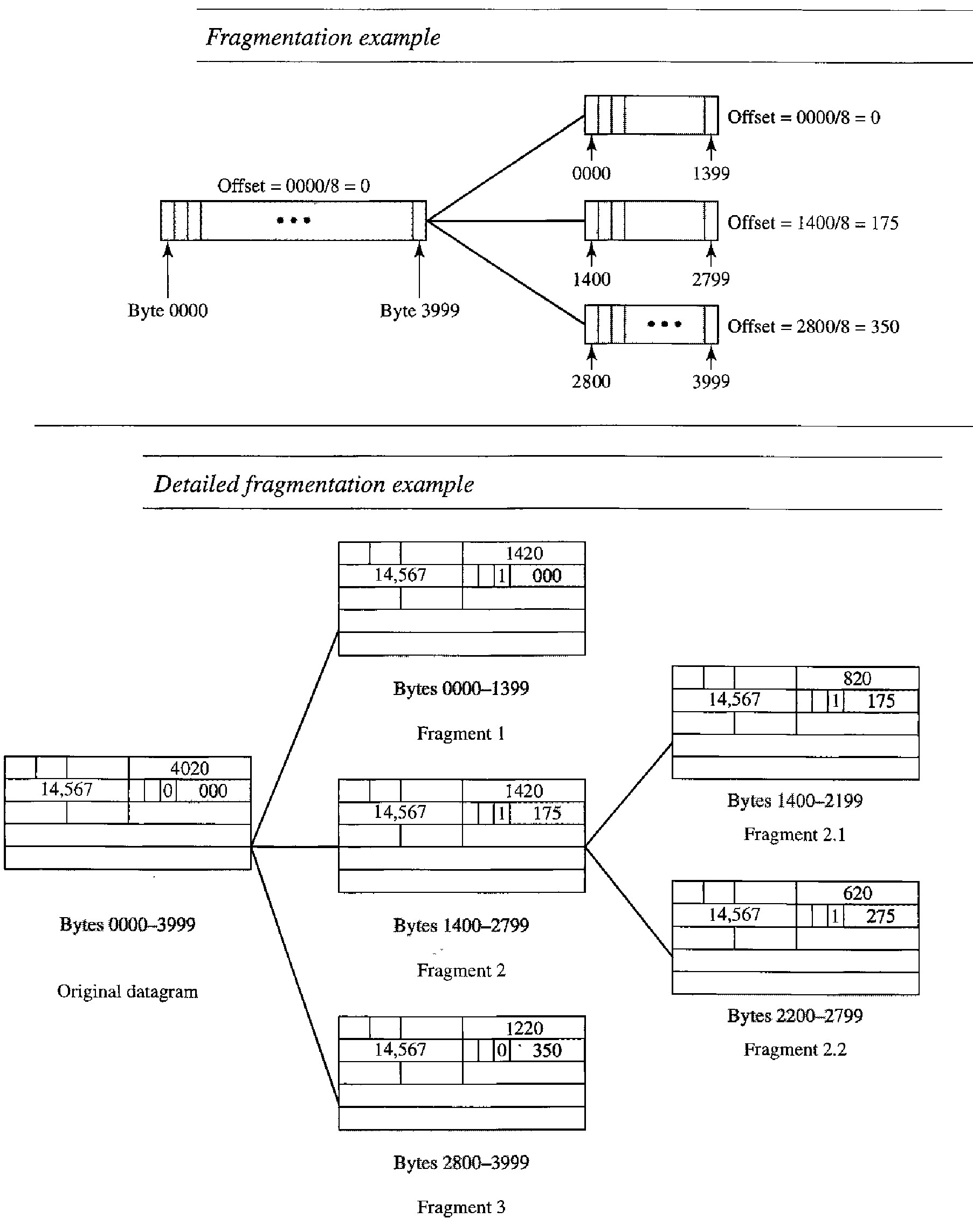
This 13-bit field shows the relative position of this fragment with respect to the whole datagram. It is the offset of the data in the original datagram measured in units of 8 bytes.
The bytes in the original datagram are numbered 0 to 3999. The first fragment carries bytes 0 to 1399. The offset for this datagram is 0/8 = 0. The second fragment carries bytes 1400 to 2799; the offset value for this fragment is 1400/8 = 175. Finally, the third fragment carries bytes 2800 to 3999. The offset value for this fragment is 2800/8 = 350.
The figure also shows what happens if a fragment itself is fragmented. In this case the value of the offset field is always relative to the original datagram. For example, in the figure, the second fragment is itself fragmented later to two fragments of 800 bytes and 600 bytes, but the offset shows the relative position of the fragments to the original data.
Q. A packet has arrived with an M bit value of O. Is this the first fragment, the last fragment, or a middle fragment? Do we know if the packet was fragmented?
If the M bit is 0, it means that there are no more fragments; the fragment is the last one. However, we cannot say if the original packet was fragmented or not. A nonfragmented packet is considered the last fragment.
Q. A packet has arrived with an M bit value of 1. Is this the first fragment, the last fragment, or a middle fragment? Do we know if the packet was fragmented?
If the M bit is 1, it means that there is at least one more fragment. This fragment can be the first one or a middle one, but not the last one. We don't know if it is the first one or a middle one; we need more information (the value of the fragmentation offset).
Q. A packet has arrived with an M bit value of 1 and a fragmentation offset value of O. Is this the first fragment, the last fragment, Or a middle fragment?
Because the M bit is 1, it is either the first fragment or a middle one. Because the offset value is 0, it is the first fragment.
Q. A packet has arrived in which the offset value is 100. What is the number of the first byte? Do we know the number of the last byte?
To find the number of the first byte, we multiply the offset value by 8. This means that the first byte number is 800. We cannot determine the number of the last byte unless we know the length of the data.
Q. A packet has arrived in which the offset value is 100, the value of HLEN is 5, and the value of the total length field is 100. What are the numbers of the first byte and the last byte?
The first byte number is 100 x 8 = 800. The total length is 100 bytes, and the header length is 20 bytes (5 x 4), which means that there are 80 bytes in this datagram. If the first byte number is 800, the last byte number must be 879.
Checksum
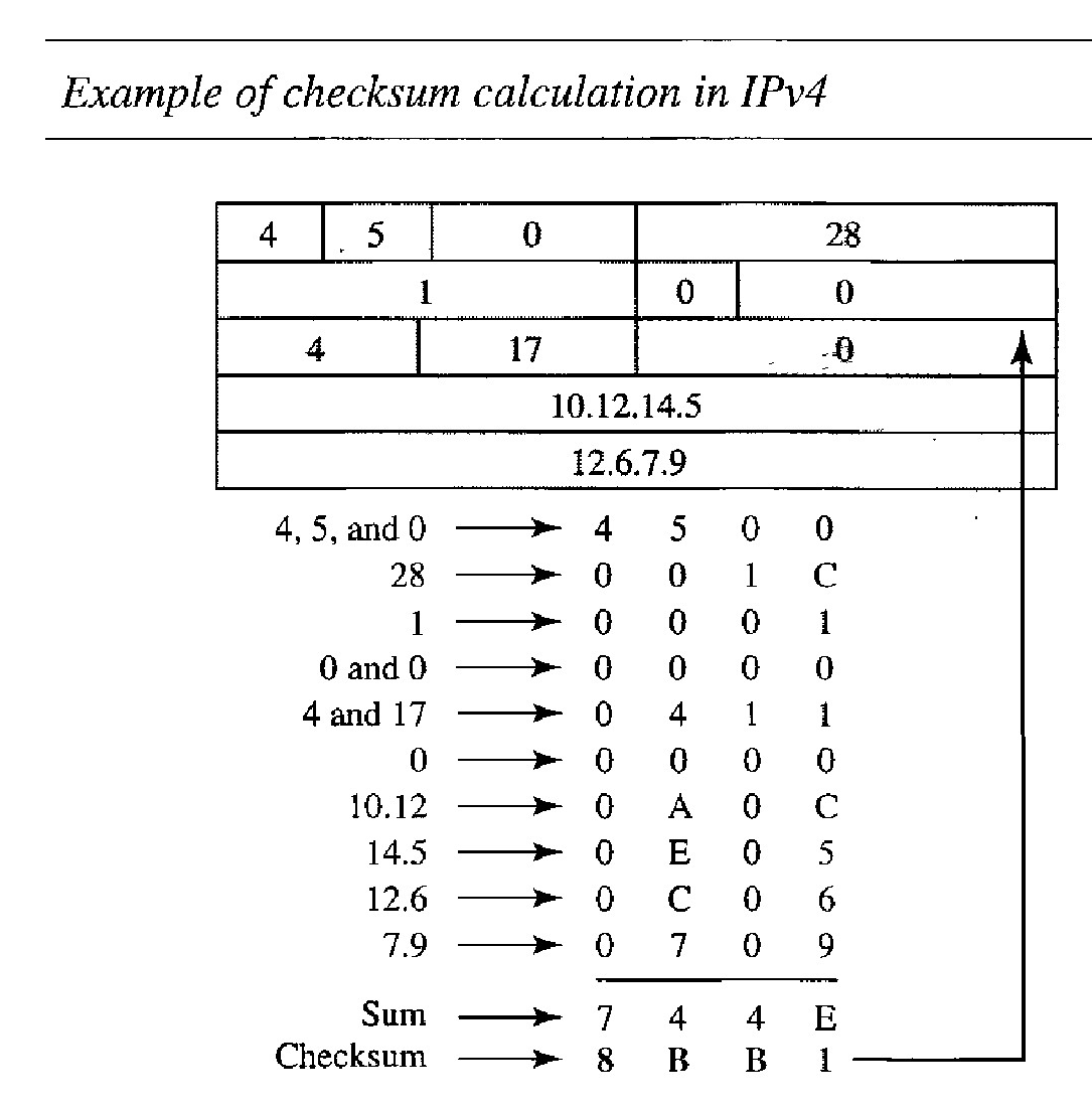
The implementation of the checksum in the IPv4 packet follows the steps given. First, the value of the checksum field is set to O. Then the entire header is divided into 16-bit sections and added together. The result (sum) is complemented and inserted into the checksum field.
The checksum in the IPv4 packet covers only the header, not the data. There are two good reasons for this. First, all higher-level protocols that encapsulate data in the IPv4 datagram have a checksum field that covers the whole packet. Therefore, the checksum for the IPv4 datagram does not have to check the encapsulated data.
Second, the header of the IPv4 packet changes with each visited router, but the data do not. So the checksum includes only the part that has changed. If the data were included, each router must recalculate the checksum for the whole packet, which means an increase in processing time.
Figure below shows an example of a checksum calculation for an IPv4 header without options. The header is divided into 16-bit sections. All the sections are added and the sum is complemented. The result is inserted in the checksum field.
Options
The header of the IPv4 datagram is made of two parts: a fixed part and a variable part. The fixed part is 20 bytes long and the variable part comprises the options that can be a maximum of 40 bytes.
Options, as the name implies, are not required for a datagram. They can be used for network testing and debugging. Although options are not a required part of the IPv4 header, option processing is required of the IPv4 software. This means that all implementations must be able to handle options if they are present in the header.
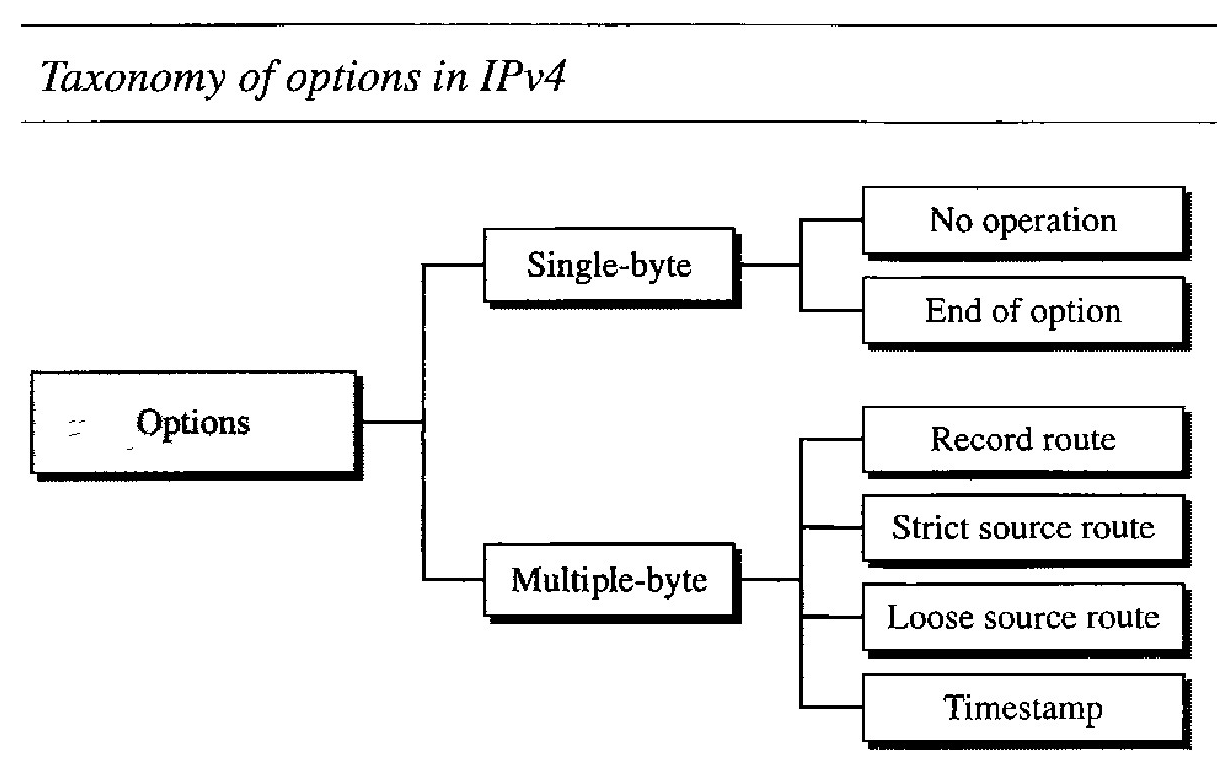
Taxonomy of options in IPv4
A no-operation option is a l-byte option used as a filler between options.
An end-of-option option is a 1-byte option used for padding at the end of the option field. It, however, can only be used as the last option.
A record route option is used to record the Internet routers that handle the datagram. It can list up to nine router addresses. It can be used for debugging and management purposes.
A strict source route option is used by the source to predetermine a route for the datagram as it travels through the Internet.
A loose source route option is similar to the strict source route, but it is less rigid. Each router in the list must be visited, but the datagram can visit other routers as well.
A timestamp option is used to record the time of datagram processing by a router. The time is expressed in milliseconds from midnight, Universal time or Greenwich mean time.
IPv6
IPv6 (Internetworking Protocol, version 6), also known as IPng (Internetworking Protocol, next generation), was proposed and is now a standard. In IPv6, the Internet protocol was extensively modified to accommodate the unforeseen growth of the Internet.
The adoption of IPv6 has been slow. The reason is that the original motivation for its development, depletion of IPv4 addresses, has been remedied by short-term strategies such as classless addressing and NAT. However, the fast-spreading use of the Internet, and new services such as mobile IP, IP telephony, and IP-capable mobile telephony, may eventually require the total replacement of IPv4 with IPv6.
The next-generation IP, or IPv6, has some advantages over IPv4 that can be summarized as follows:
Larger address spaceAn IPv6 address is 128 bits long, as we discussed in Chapter 19. Compared with the 32-bit address of IPv4, this is a huge (296) increase in the address space.
Better header format. IPv6 uses a new header format in which options are separated from the base header and inserted, when needed, between the base header and the upper-layer data. This simplifies and speeds up the routing process because most of the options do not need to be checked by routers.
Support for resource allocation. In IPv6, the type-of-service field has been removed, but a mechanism (calledfiow label) has been added to enable the source to request special handling of the packet. This mechanism can be used to support traffic such as real-time audio and video.
Support for more securityThe encryption and authentication options in IPv6 provide confidentiality and integrity of the packet.
NETWORK LAYER: INTERNET PROTOCOL (IPv6 packet)
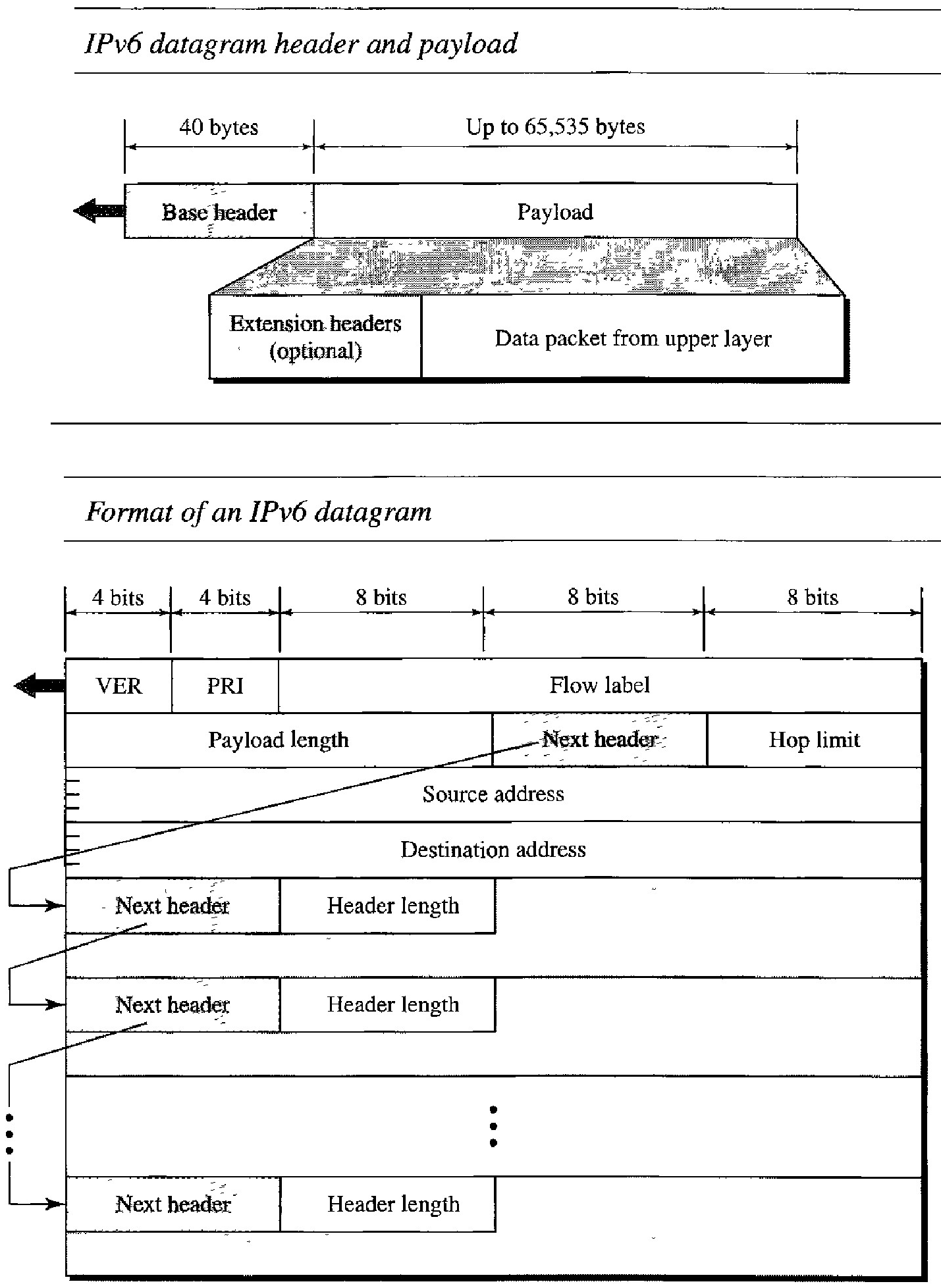
Each packet is composed of a mandatory base header followed by the payload. The payload consists of two parts: optional extension headers and data from an upper layer. The base header occupies 40 bytes, whereas the extension headers and data from the upper layer contain up to 65,535 bytes of information.
Version : This 4-bit field defines the version number of the IP. For IPv6, the value is 6.
Priority : The 4-bit priority field defines the priority of the packet with respect to traffic congestion.
Flow label: The flow label is a 3-byte (24-bit) field that is designed to provide special handling for a particular flow of data.
Payload length : The 2-byte payload length field defines the length of the IP datagram excluding the base header
Next header : The next header is an 8-bit field defining the header that follows the base header in the datagram. The next header is either one of the optional extension headers used by IP or the header of an encapsulated packet such as UDP or TCP. Each extension header also contains this field
Hop limit : This 8-bit hop limit field serves the same purpose as the TTL field in 1Pv4
Source address : The source address field is a 16-byte (128-bit) Internet address that identifies the original source of the datagram
Destination address : The destination address field is a 16-byte (128-bit) Internet address that usually identifies the final destination of the datagram. However, if source routing is used, this field contains the address of the next router.