Switching
A network is a set of connected devices. Whenever we have multiple devices, we have the problem of how to connect them to make one-to-one communication possible. One solution is to make a point-to-point connection between each pair of devices (a mesh topology) or between a central device and every other device (a star topology).
These methods, however, are impractical and wasteful when applied to very large networks. The number and length of the links require too much infrastructure to be cost-efficient, and the majority of those links would be idle most of the time.
Other topologies employing multipoint connections, such as a bus, are ruled out because the distances between devices and the total number of devices increase beyond the capacities of the media and equipment.
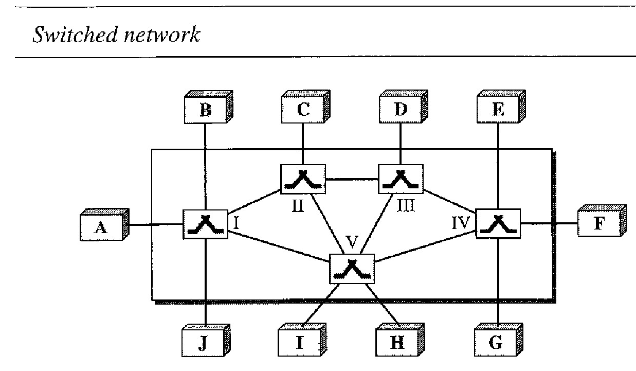
A better solution is switching. A switched network consists of a series of interlinked nodes, called switches. Switches are devices capable of creating temporary connections between two or more devices linked to the switch. In a switched network, some of these nodes are connected to the end systems (computers or telephones, for example). Others are used only for routing.
The end systems (communicating devices) are labeled A, E, C, D, and so on, and the switches are labeled I, II, III, IV, and V. Each switch is connected to multiple links.
Traditionally, three methods of switching have been important: circuit switching, packet switching, and message switching. The first two are commonly used today. The third has been phased out in general communications but still has networking applications.
Packet-switched networks can further be divided into two subcategories - virtual-circuit networks and datagram networks.
CIRCUIT-SWITCHED NETWORKS
A circuit-switched network consists of a set of switches connected by physical links. A connection between two stations is a dedicated path made of one or more links. However, each connection uses only one dedicated channel on each link.
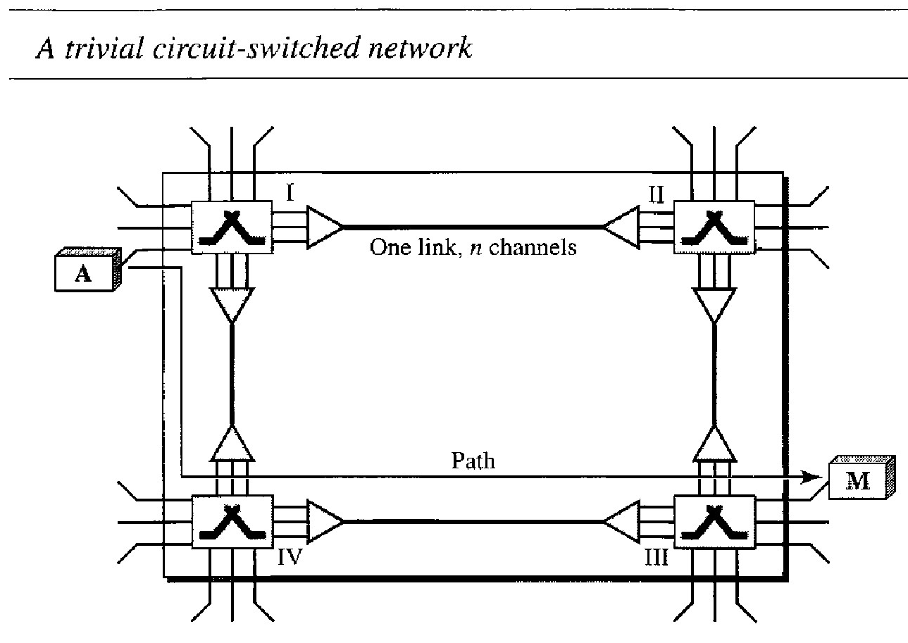
Figure below shows a trivial circuit-switched network with four switches and four links. Each link is divided into n (n is 3 in the figure) channels by using FDM or TDM.
The end systems, such as computers or telephones, are directly connected to a switch. We have shown only two end systems for simplicity. When end system A needs to communicate with end system M :
System A needs to request a connection to M that must be accepted by all switches as well as by M itself. This is called the setup phase.
A circuit (channel) is reserved on each link, and the combination of circuits or channels defines the dedicated path. After the dedicated path made of connected circuits (channels) is established, data transfer can take place.
After all data have been transferred, the circuits are tom down.
Key notes about Circuit Switching :
Circuit switching takes place at the physical layer.
Before starting communication, the stations must make a reservation for the resources to be used during the communication. These resources, such as channels (bandwidth in FDM and time slots in TDM), switch buffers, switch processing time, and switch input/output ports, must remain dedicated during the entire duration of data transfer until the teardown phase.
Data transferred between the two stations are not packetized (physical layer transfer of the signal). The data are a continuous flow sent by the source station and received by the destination station, although there may be periods of silence.
There is no addressing involved during data transfer. The switches route the data based on their occupied band (FDM) or time slot (TDM). Of course, there is end-to-end addressing used during the setup phase.
Example 1: circuit-switched network
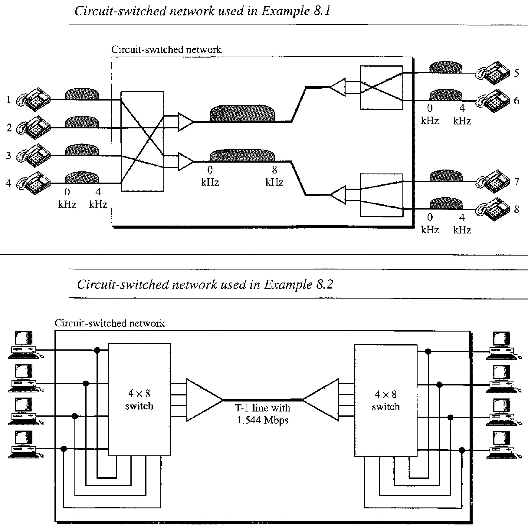
let us use a circuit-switched network to connect eight telephones in a small area. Communication is through 4-kHz voice channels.
We assume that each link uses two voice channels. The bandwidth of each link is then 8 kHz.
Telephone 1 is connected to telephone 7; 2 to 5; 3 to 8; and 4 to 6. Of course the situation may change when new connections are made. The switch controls the connections.
Example 2: circuit-switched network
As another example, consider a circuit-switched network that connects computers in two remote offices of a private company.
The offices are connected using a T-l line leased from a communication service provider. There are two 4 X 8 (4 inputs and 8 outputs) switches in this network.
For each switch, four output ports are folded into the input ports to allow communication between computers in the same office. Four other output ports allow communication between the two offices.
Efficiency
It can be argued that circuit-switched networks are not as efficient as the other two types of networks because resources are allocated during the entire duration ofthe connection.
These resources are unavailable to other connections. In a telephone network, people normally terminate the communication when they have finished their conversation.
However, in computer networks, a computer can be connected to another computer even if there is no activity for a long time.
In this case, allowing resources to be dedicated means that other connections are deprived.
Delay
Although a circuit-switched network normally has low efficiency, the delay in this type of network is minimal.
During data transfer, the data are not delayed at each switch; the resources are allocated for the duration of the connection.
There is no waiting time at each switch. The total delay is due to the time needed to create the connection, transfer data, and disconnect the circuit.
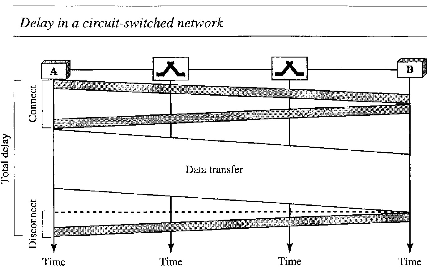
Below figure shows the delay : The delay caused by the setup is the sum of four parts
The propagation time of the source computer request (slope of the first gray box), the request signal transfer time (height of the first gray box), the propagation time of the acknowledgment from the destination computer (slope of the second gray box), and the signal transfer time of the acknowledgment (height of the second gray box).
The delay due to data transfer is the sum of two parts: the propagation time (slope of the colored box) and data transfer time (height of the colored box), which can be very long.
The third box shows the time needed to tear down the circuit. We have shown the case in which the receiver requests disconnection, which creates the maximum delay.
DATAGRAM NETWORKS
In data communications, we need to send messages from one end system to another. If the message is going to pass through a packet-switched network, it needs to be divided into packets of fixed or variable size. The size of the packet is determined by the network and the governing protocol.
In packet switching, there is no resource allocation for a packet. This means that there is no reserved bandwidth on the links, and there is no scheduled processing time for each packet.
Resources are allocated on demand. The allocation is done on a firstcome, first-served basis. When a switch receives a packet, no matter what is the source or destination, the packet must wait if there are other packets being processed.
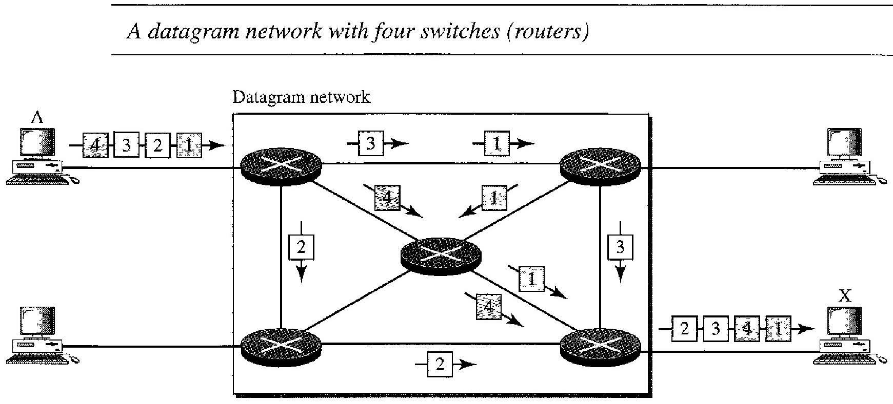
In a datagram network, each packet is treated independently of all others. Even if a packet is part of a multipacket transmission, the network treats it as though it existed alone. Packets in this approach are referred to as datagrams.
Figure above shows how the datagram approach is used to deliver four packets from station A to station X. The switches in a datagram network are traditionally referred to as routers.
In this example, all four packets (or datagrams) belong to the same message, but may travel different paths to reach their destination.
This is so because the links may be involved in carrying packets from other sources and do not have the necessary bandwidth available to carry all the packets from A to X.
This approach can cause the datagrams of a transmission to arrive at their destination out of order with different delays between the packets. Packets may also be lost or dropped because of a lack of resources.
In most protocols, it is the responsibility of an upper-layer protocol to reorder the datagrams or ask for lost datagrams before passing them on to the application.
The datagram networks are sometimes referred to as connectionless networks. The term connectionless here means that the switch (packet switch) does not keep information about the connection state. There are no setup or teardown phases. Each packet is treated the same by a switch regardless of its source or destination.
Switching in the Internet is done by using the datagram approach to packet switching at the network layer.
Routing Table
In this type of network, each switch (or packet switch) has a routing table which is based on the destination address. The routing tables are dynamic and are updated periodically.
The destination addresses and the corresponding forwarding output ports are recorded in the tables. This is different from the table of a circuit switched network in which each entry is created when the setup phase is completed and deleted when the teardown phase is over.
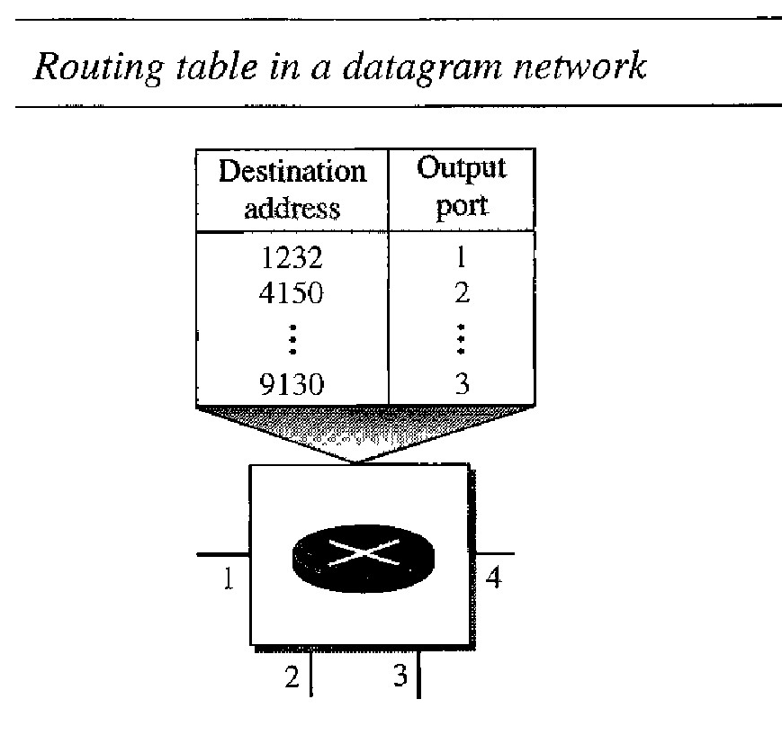
Destination Address
Every packet in a datagram network carries a header that contains, among other information, the destination address of the packet.
When the switch receives the packet, this destination address is examined; the routing table is consulted to find the corresponding port through which the packet should be forwarded.
This address, unlike the address in a virtual-circuit-switched network, remains the same during the entire journey of the packet.
Efficiency
The efficiency of a datagram network is better than that of a circuit-switched network; resources are allocated only when there are packets to be transferred.
If a source sends a packet and there is a delay of a few minutes before another packet can be sent, the resources can be reallocated during these minutes for other packets from other sources.
Delay
There may be greater delay in a datagram network than in a virtual-circuit network. Although there are no setup and teardown phases, each packet may experience a wait at a switch before it is forwarded.
In addition, since not all packets in a message necessarily travel through the same switches, the delay is not uniform for the packets of a message.
The packet travels through two switches. There are three transmission times (3T), three propagation delays (slopes 3L of the lines), and two waiting times (W1 + W2). We ignore the processing time in each switch.
The total delay is = 3T + 3L + W1 + W2
VIRTUAL-CIRCUIT NETWORKS
A virtual-circuit network is a cross between a circuit-switched network and a datagram network.
As in a circuit-switched network, there are setup and teardown phases in addition to the data transfer phase.
Resources can be allocated during the setup phase, as in a circuit-switched network, or on demand, as in a datagram network.
As in a datagram network, data are packetized and each packet carries an address in the header. However, the address in the header has local jurisdiction (it defines what should be the next switch and the channel on which the packet is being carried), not end-to-end jurisdiction.
As in a circuit-switched network, all packets follow the same path established during the connection.
A virtual-circuit network is normally implemented in the data link layer, while a circuit-switched network is implemented in the physical layer and a datagram network in the network layer.
The network has switches that allow traffic from sources to destinations. A source or destination can be a computer, packet switch, bridge, or any other device that connects other networks.
Virtual-circuit network addressing : global and local (virtual-circuit identifier).
Global Addressing : A source or a destination needs to have a global address - an address that can be unique in the scope of the network or internationally if the network is part of an international network.
Virtual-Circuit Identifier : The identifier that is actually used for data transfer is called the virtual-circuit identifier (Vel).
Virtual-circuit network: setup, data transfer, and teardown
Setup phase :
In the setup phase, the source and destination use their global addresses to help switches make table entries for the connection.
In the setup phase, a switch creates an entry for a virtual circuit. For example, suppose source A needs to create a virtual circuit to B. Two steps are required: the setup request and the acknowledgment.
Data Transfer Phase
To transfer a frame from a source to its destination, all switches need to have a table entry for this virtual circuit.
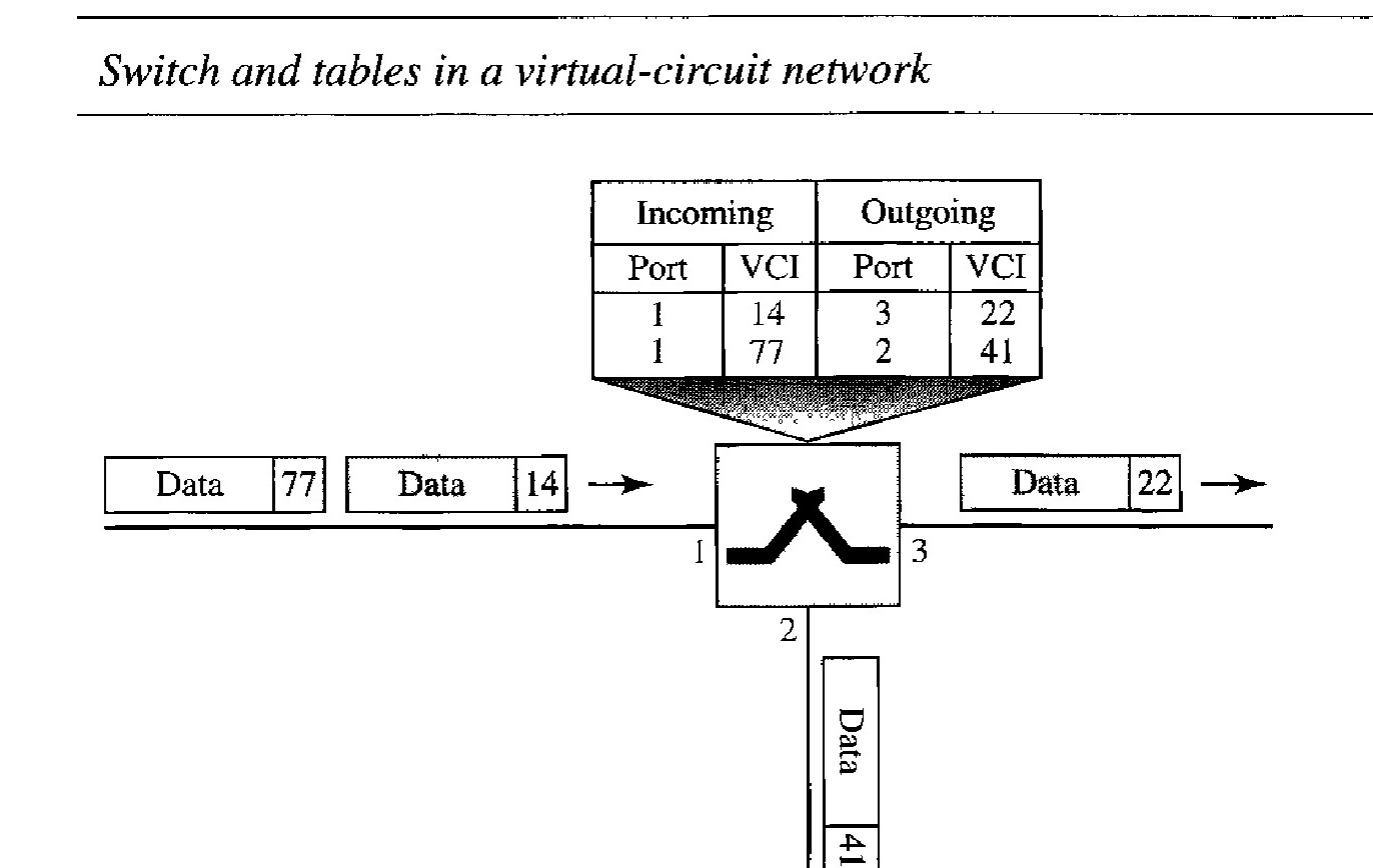
The table, in its simplest form, has four columns. This means that the switch holds four pieces of information for each virtual circuit that is already set up.
Figure below shows a frame arriving at port 1 with a VCI of 14. When the frame arrives, the switch looks in its table to find port 1 and a VCI of 14. When it is found, the switch knows to change the VCI to 22 and send out the frame from port 3.
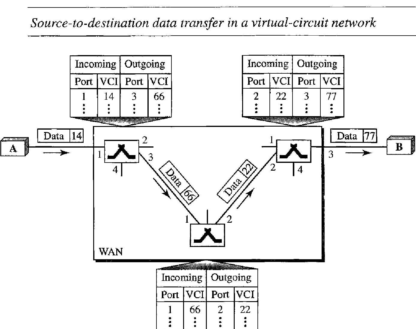
Figure below shows how a frame from source A reaches destination B and how its VCI changes during the trip. Each switch changes the VCI and routes the frame.
The data transfer phase is active until the source sends all its frames to the destination. The procedure at the switch is the same for each frame of a message. The process creates a virtual circuit, not a real circuit, between the source and destination.
Teardown phase :
In the teardown phase, the source and destination inform the switches to delete the corresponding entry. Data transfer occurs between these two phases. In this phase, source A, after sending all frames to B, sends a special frame called a teardown request. Destination B responds with a teardown confirmation frame. All switches delete the corresponding entry from their tables.
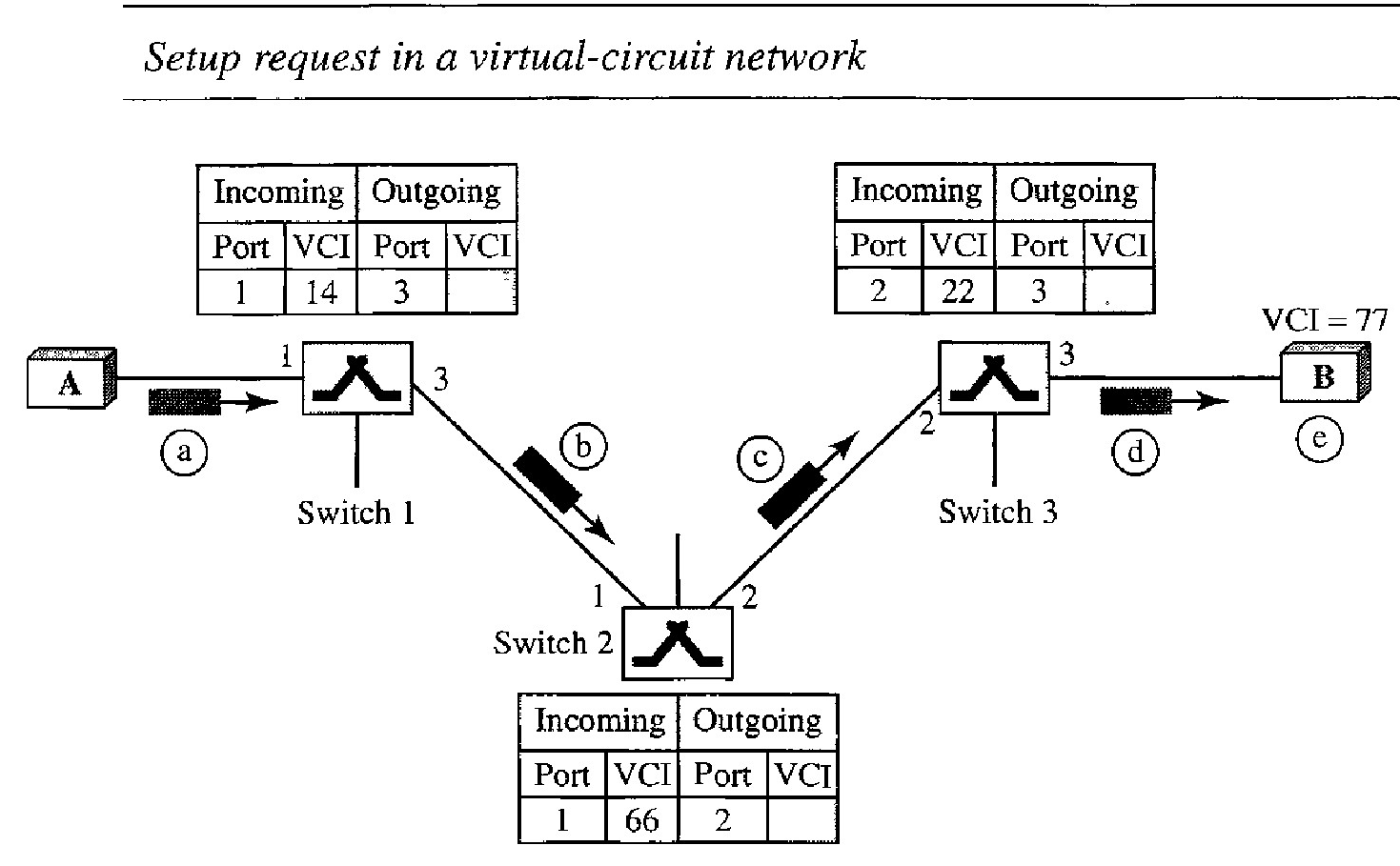
Setup Request : Virtual-circuit network
A setup request frame is sent from the source to the destination. Figure below shows the process.
Source A sends a setup frame to switch 1.
The switch, in the setup phase, acts as a packet switch; it has a routing table which is different from the switching table.
The switch creates an entry in its table for this virtual circuit, but it is only able to fill three of the four columns.
The switch assigns the incoming port (1) and chooses an available incoming VCI (14) and the outgoing port (3).
It does not yet know the outgoing VCI, which will be found during the acknowledgment step. The switch then forwards the frame through port 3 to switch 2.
Switch 2 receives the setup request frame. The same events happen here as at switch 1; three columns of the table are completed: in this case, incoming port (l ), incoming VCI (66), and outgoing port (2).
Switch 3 receives the setup request frame. Again, three columns are completed: incoming port (2), incoming VCI (22), and outgoing port (3).
Destination B receives the setup frame, and if it is ready to receive frames from A, it assigns a VCI to the incoming frames that come from A, in this case 77. This VCI lets the destination know that the frames come from A, and not other sources.
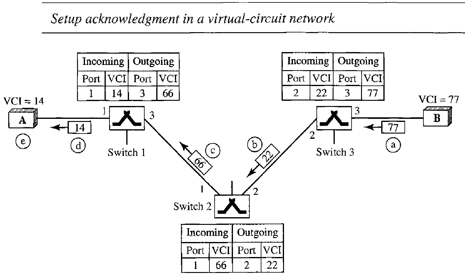
Acknowledgment : A special frame, called the acknowledgment frame, completes the entries in the switching tables. Figure below shows the process.
The destination sends an acknowledgment to switch 3. The acknowledgment carries the global source and destination addresses so the switch knows which entry in the table is to be completed.
The frame also carries VCI 77, chosen by the destination as the incoming VCI for frames from A. Switch 3 uses this VCI to complete the outgoing VCI column for this entry. Note that 77 is the incoming VCI for destination B, but the outgoing VCI for switch 3.
Switch 3 sends an acknowledgment to switch 2 that contains its incoming VCI in the table, chosen in the previous step. Switch 2 uses this as the outgoing VCI in the table.
Switch 2 sends an acknowledgment to switch 1 that contains its incoming VCI in the table, chosen in the previous step. Switch 1 uses this as the outgoing VCI in the table.
Finally switch 1 sends an acknowledgment to source A that contains its incoming VCI in the table, chosen in the previous step.
The source uses this as the outgoing VCI for the data frames to be sent to destination B.
Efficiency
Resource reservation in a virtual-circuit network can be made during the setup or can be on demand during the data transfer phase.
In the first case, the delay for each packet is the same; in the second case, each packet may encounter different delays.
There is one big advantage in a virtual-circuit network even if resource allocation is on demand. The source can check the availability of the resources, without actually reserving it.
In virtual-circuit switching, all packets belonging to the same source and destination travel the same path; but the packets may arrive at the destination with different delays if resource allocation is on demand.
Delay in Virtual-Circuit Networks
In a virtual-circuit network, there is a one-time delay for setup and a one-time delay for teardown. If resources are allocated during the setup phase, there is no wait time for individual packets.
The packet is traveling through two switches (routers). There are three transmission times (3T), three propagation times (3PT) , data transfer depicted by the sloping lines, a setup delay (which includes transmission and propagation in two directions), and a teardown delay (which includes transmission and propagation in one direction).
Total delay = 3T + 3PT + setup delay + teardown delay
STRUCTURE OF A SWITCH
Circuit switching can use either of two technologies: the space-division switch or the time-division switch.
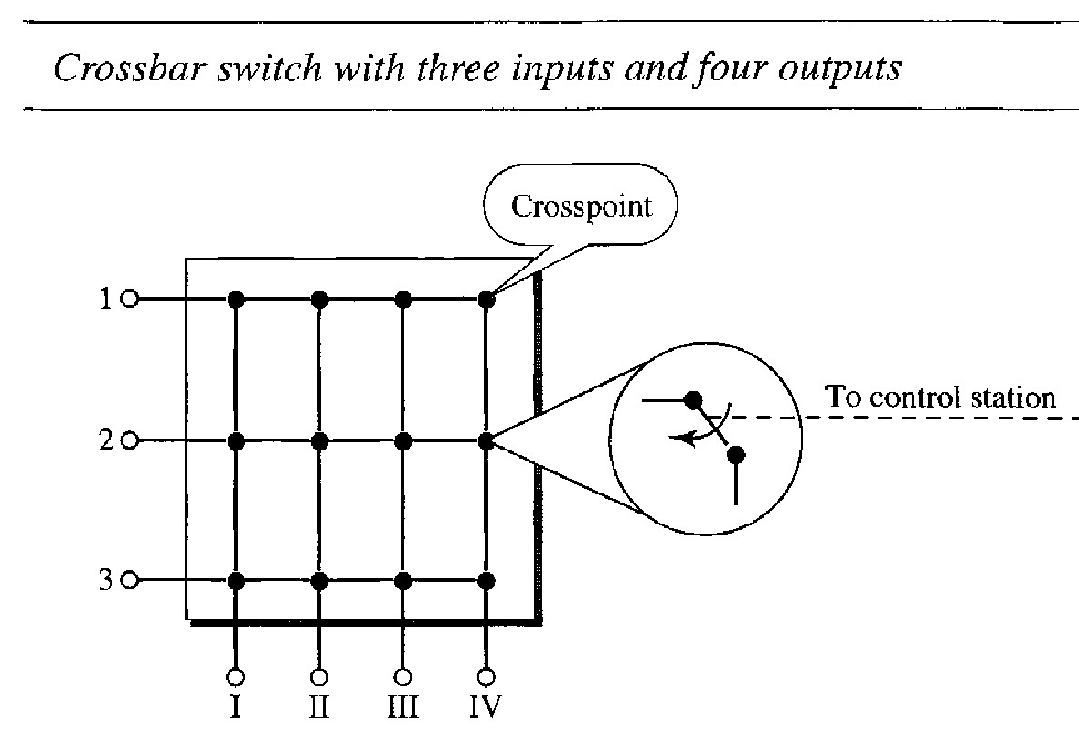
In space-division switching, the paths in the circuit are separated from one another spatially. This technology was originally designed for use in analog networks but is used currently in both analog and digital networks.
Crossbar Switch : A crossbar switch connects 'n' inputs to 'm' outputs in a grid, using electronic microswitches (transistors) at each crosspoint. The major limitation of this design is the number of crosspoints required. To connect 'n' inputs to 'm' outputs using a crossbar switch requires n x m crosspoints. For example, to connect 1000 inputs to 1000 outputs requires a switch with 1,000,000 crosspoints. A crossbar with this number of crosspoints is impractical. Such a switch is also inefficient because statistics show that, in practice, fewer than 25 percent of the crosspoints are in use at any given time. The rest are idle.
Multistage Switch : The solution to the limitations of the crossbar switch is the multistage switch, which combines crossbar switches in several (normally three) stages. In a single crossbar switch, only one row or column (one path) is active for any connection. So we need N x N crosspoints. If we can allow multiple paths inside the switch, we can decrease the number of crosspoints. Each crosspoint in the middle stage can be accessed by multiple crosspoints in the first or third stage.
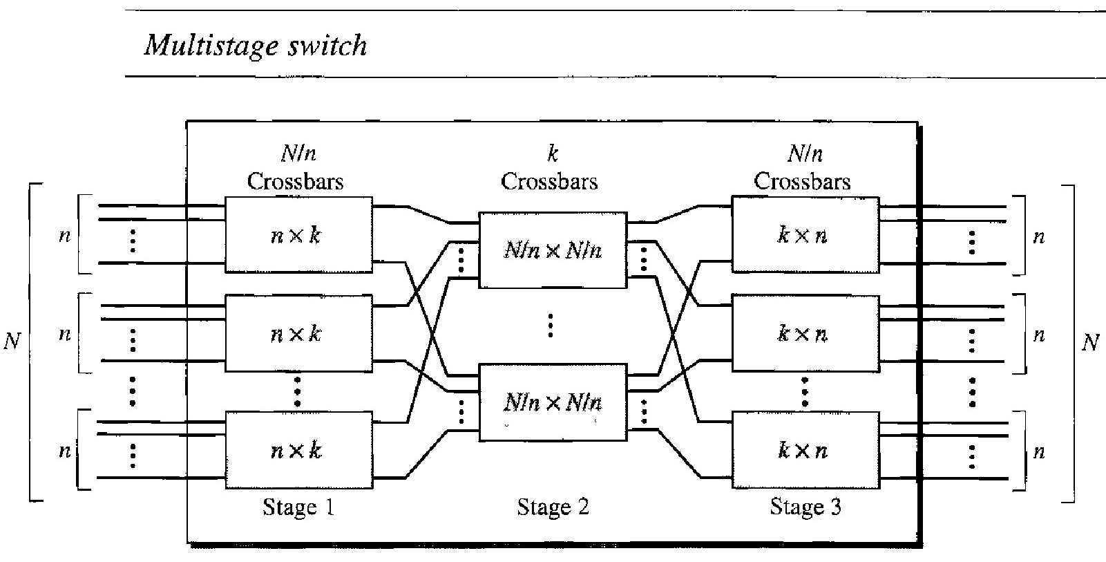
To design a three-stage switch, we follow these steps
We divide the 'N' input lines into groups, each of 'n' lines. For each group, we use one crossbar of size n x k, where k is the number of crossbars in the middle stage. In other words, the first stage has N/n crossbars of n x k crosspoints.
We use k crossbars, each of size (N/n) x (N/n) in the middle stage.
We use N/n crossbars, each of size k x n at the third stage.
We can calculate the total number of crosspoints as follows: \( \frac{N}{n} (n * k) + k(\frac{N}{n} * \frac{N}{n}) + \frac{N}{n} (k*n)\)
Total number of crosspoints = \( 2kN + k(\frac{N}{n})^2\)
Q : Design a three-stage, 200 x 200 switch (N = 200) with k = 4 and n = 20.
In the first stage we have N/n or 10 crossbars, each of size 20 x 4.
In the second stage, we have 4 crossbars, each of size 10 x 10. In the third stage, we have 10 crossbars, each of size 4 x 20.
The total number of crosspoints is \( 2kN + k(\frac{N}{n})^2\), or 2000 crosspoints. This is 5 percent of the number of crosspoints in a single-stage switch (200 x 200 = 40,000).
Clos Criteria and Multistage Switching
The multistage switch has one drawback-blocking during periods of heavy traffic. The whole idea of multistage switching is to share the crosspoints in the middle-stage crossbars. Sharing can cause a lack of availability if the resources are limited and all users want a connection at the same time. Blocking refers to times when one input cannot be connected to an output because there is no path available between them-all the possible intermediate switches are occupied.
In a single-stage switch, blocking does not occur because every combination of input and output has its own crosspoint; there is always a path.
Clos investigated the condition of nonblocking in multistage switches and came up with the following formula. In a nonblocking switch, the number of middle-stage switches must be at least 2n - 1. In other words, we need to have k ≥ 2n - 1
According to Clos criterion :
\( n = \frac{N}{2}^{\frac{1}{2}} \)
k > 2n-1
Total number of crosspoints ≥ \(4N [(2N)^{\frac{1}{2}} - 1]\)
Q. Redesign the previous three-stage, 200 x 200 switch, using the Clos criteria with a minimum number of crosspoints.
We let n =(200/2)^0.5, or n = 10. We calculate k = 2n - 1 = 19. In the first stage, we have 200 / 10, or 20, crossbars, each with 10 * 19 crosspoints. In the second stage, we have 19 crossbars, each with 10 * 10 crosspoints.
n the third stage, we have 20 crossbars each with 19 X 10 crosspoints. The total number of crosspoints is 20(10 x 19) + 19(10 x 10) + 20(19 * 10) = 9500.
If we use a single-stage switch, we need 200 x 200 = 40,000 crosspoints. The number of crosspoints in this three-stage switch is 24 percent that of a single-stage switch.