Points to Remember - Digital Design
Range of n bit 2's complement number:-
\( - 2^{(n-1)} \text{ to } (2^{(n-1)} - 1) \)
Range of n bit 1's complement number:-
\( -(2^{(n-1)} - 1) \text{ to } (2^{(n-1)} - 1) \)
Implicant:- A normal product term that implies Y
Y = AB + BC + ABC; (AB, BC, ABC are known as implicants.
Prime Implicant:- An implicant of Y such that if any variable is removed from the implicant, the resulting term doesn't imply Y.
Y = AB + BC + ABC; (AB, BC are prime implicants but ABC is not a prime implicant.
Essential Prime Implicant:- If a minterm is covered only by a prime implicant, then the prime implicant is known as an Essential Prime Implicant
Y = AB + BC + ABC; (AB, BC are prime implicants but ABC is not a prime implicant.
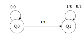
Finite State Machine to calculate 2's complement:- Input is from least significant bit.
Characteristic Equation: An equation which expresses the next state of the flip flop in terms of its present state and inputs.
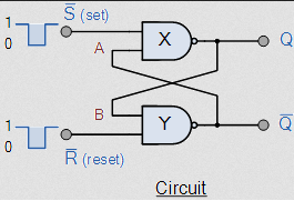
S - R Flip Flop (SET - RESET)
Characteristic Equation of SR Flipflop: \( Q^t = S + R'Q \)
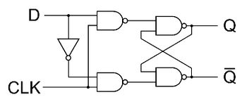
D - FlipFlop (Delay Flipflop)
Characteristic Equation of Delay Flipflop : Qt = D
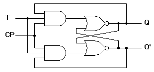
Trigger flip flop : T - Flip Flop
Characteristic Equation of Trigger Flipflop : Qt = T'Q + TQ'.
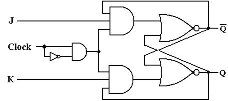
J - K Flip Flop
Characteristic Equation of J - K Flip Flop : Qt = QK' + Q'J
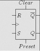
Clocked flipflops with clear and preset inputs
A '0' applied to the clear input will reset the flip flop to Q = 0.
A '0' applied to the preset input will reset the flip flop to Q = 1.
The above inputs override the clock and the J-K inputs
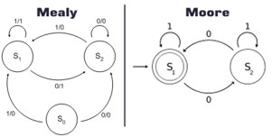
Moore machine: If the output of the sequential network is a function of the present state only , the network is referred to as a Moore machine.
Mealy machine: If the output of the sequential network is a function of both the present state and the input , the network is referred to as a Mealy machine.
Positive logic: +V represents a logic of 1 and 0 volts represents a logic of 0.
Negative logic: +V represents a logic of 0 and 0 volts represents a logic of 1.
To find the minimum number of gates needed to solve the expression, one must find both the network with the AND gate output and the one with the OR gate output.
Multiplexer: A multiplexer has a group of data inputs and a group of control inputs. The control inputs are used to select one of the data inputs and connect it to the output terminal.
A 2n to 1 multiplexer can be used to realize any (n + 1) variable function with n0 added gates.
'n' of the variables are used as control inputs and the remaining variable is used as required on the data inputs.
Equation of multipler: Z = A'B'I0 + A'BI1 + AB'I2 + ABI3
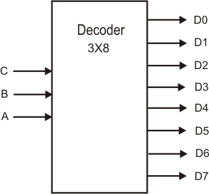
Decoder: It is a combinational logic circuit that converts binary information from 'n' input lines to a maximum of 2n unique output lines.
Encoder: It is a combinational logic circuit that has 2n or fewer input lines and unique output lines. Hence it is reverse of the decoder.
Multiplexer application: Data routing, Function generator, Parallel to serial converter.
Demultiplexer application: Serial to parallel conversion.
Shift register application: Time delay, serial to parallel data converter, parallel to serial data converter.
Canonical Logic Form: If each term in SOP and POS contains all literals then it is known as canonical or standard form expression.
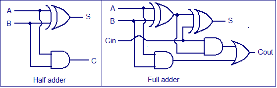
Half Adder:
S = A ⊕ B
C = A.B
Full Adder:
S = A ⊕ B ⊕ Cin
Cout = ( A ⊕ B ) Cin + A.B
Carry Look Ahead Adder:
\( P_i = A_i \oplus B_i \)
\( G_i = A_i \cdot B_i \)
\( S_i = P_i \oplus C_i \)
\( C_{i+1} = G_i + P_i . C_i \)
for i = 0
\( C_1 = G_0 + P_0 . C_0 \)
for i = 1
\( C_2 = G_1 + P_1 . C_1 \)
\( C_2 = G_1 + P_1 . (G_0 + P_0 . C_0) \)
for i = 2
\( C_3 = G_2 + P_2 . C_2 \)
\( C_3 = G_2 + P_2 . ( G_1 + P_1 . (G_0 + P_0 . C_0)) \)
for i = 3
\( C_4 = G_3 + P_3 . C_3 \)
\( C_3 = G_3 + P_3 . (G_2 + P_2 . (G_1 + P_1 . (G_0 + P_0 . C_0)) \)
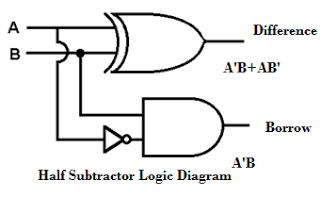
Half Substractor:
D = A ⊕ B
B(out) = A'.B
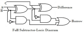
Full Substractor:
D = A ⊕ B ⊕ Bin
B(out) = ( A ⊕ B )'.Bin + A'.B
Reduction of State Tables:
Elimination of redundant states:
Determination of state equivalence using an equivalence table.
Finite State Machine - Digital Design
S - R Flip Flop (SET - RESET) - Digital Design
| S(t) | R(t) | Q(t) | Q(t + ε) |
|---|---|---|---|
| 0 | 0 | 0 | 0 |
| 0 | 0 | 1 | 1 |
| 0 | 1 | 0 | 0 |
| 0 | 1 | 1 | 0 |
| 1 | 0 | 0 | 1 |
| 1 | 0 | 1 | 1 |
| 1 | 1 | 0 | -- (input not allowed) |
| 1 | 1 | 1 | -- (input not allowed) |
D - FlipFlop (Delay Flipflop) - Digital Design
| D | Q | Qt |
|---|---|---|
| 0 | 0 | 0 |
| 0 | 1 | 0 |
| 1 | 0 | 1 |
| 1 | 1 | 1 |
Trigger flip flop : T - Flip Flop - Digital Design
| T | Q | Qt |
|---|---|---|
| 0 | 0 | 0 |
| 0 | 1 | 1 |
| 1 | 0 | 1 |
| 1 | 1 | 0 |
J - K Flip Flop - Digital Design
| J | K | Q | Qt |
|---|---|---|---|
| 0 | 0 | 0 | 0 |
| 0 | 0 | 1 | 1 |
| 0 | 1 | 0 | 0 |
| 0 | 1 | 1 | 0 |
| 1 | 0 | 0 | 1 |
| 1 | 0 | 1 | 1 |
| 1 | 1 | 0 | 1 |
| 1 | 1 | 1 | 0 |
Clocked flipflops - Digital Design
Moore and Mealy machine - Digital Design
Mux Demux - Digital Design
Encoder and Decoder - Digital Design
Half and Full Adder - Digital Design
Half and Full substractor - Digital Design
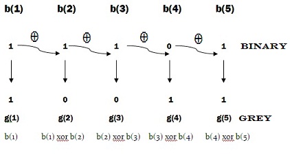
Binary to gray code conversion - Digital Design
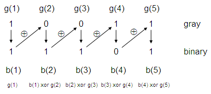
Gray to Binary code conversion - Digital Design
Reduction of State Tables - Digital Design
State Reduction
Example: Let us consider the state table of a sequential circuit shown in Table 6.
| Present State | Next State
|
Output
|
||||||||||||||||||||||||||||||
|
|
|
Table 6. State table
It can be seen from the table that the present state A and F both have the same next states, B (when x=0) and C (when x=1). They also produce the same output 1 (when x=0) and 0 (when x=1). Therefore states A and F are equivalent. Thus one of the states, A or F can be removed from the state table. For example, if we remove row F from the table and replace all F's by A's in the columns, the state table is modified as shown in Table 7.
| Present State | Next State
|
Output
|
|||||||||||||||||||||||||
|
|
|
Table 7. State F removed
It is apparent that states B and E are equivalent. Removing E and replacing E's by B's results in the reduce table shown in Table 8.
| Present State | Next State
|
Output
|
||||||||||||||||||||
|
|
|
Table 8. Reduced state table
The removal of equivalent states has reduced the number of states in the circuit from six to four. Two states are considered to be equivalent if and only if for every input sequence the circuit produces the same output sequence irrespective of which one of the two states is the starting state.