Stack Organization
A useful feature that is included in the CPU of most computers is a stack or last-in, first-out (UFO) list. A stack is a storage device that stores information in such a manner that the item stored last is the first item retrieved.
The stack in digital computers is essentially a memory unit with an address register that can count only (after an initial value is loaded into it).
The register that holds the address for the stack is called a stack pointer (SP) because its value always points at the top item in the stack.
The two operations of a stack are the insertion and deletion of items. However, nothing is pushed or popped in a computer stack. These operations are simulated by incrementing or decrementing the stack pointer register.
Register Stack A stack can be placed in a portion of a large memory or it can be organized as a collection of a finite number of memory words or registers. Figure 3 shows the organization of a 64-word register stack. The stack pointer register SP contains a binary number whose value is equal to the address of the word that is currently on top of the stack. Three items are placed in the stack: A, B, and C, in that order. Item C is on top of the stack so that the content of SP is now 3.
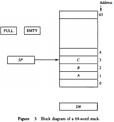
To remove the top item, the stack is popped by reading the memory word at address 3 and decrementing the content of SP.
Item B is now on top of the stack since SP holds address 2. To insert a new item, the stack is pushed by incrementing SP and writing a word in the next-higher location in the stack. Note that item C has been read out but not physically removed.
This does not matter because when the stack is pushed, a new item is written in its place. In a 64-word stack, the stack pointer contains 6 bits because 26 = 64.
Since SP has only six bits, it cannot exceed a number greater than 63 (111111 in binary). When63 is incrementedby 1, the resultis 0 since 111111 + 1 = 1000000 in binary, but SP can accommodate only the six least significant bits.
Similarly, when 000000 is decremented by 1, the result is 111111. The one-bit register FULL is set to 1 when the stack is full, and the one-bit register EMTY is set to 1 when the stack is empty of items. DR is the data register that holds the binary data to be written into or read out of the stack.
Initially, SP is cleared to 0, EMTY is set to 1, and FULL is cleared to 0, so that SP points to the word at address 0 and the stack is marked empty and not full. If the stack is not full (if FULL = 0), a new item is inserted with a push operation.
The push operation is implemented with the following sequence of microoperations;
SP ← SP + 1  Increment stack pointer
M[SP] ← DR   Write item on top of the stack
If (SP = 0) then (FULL ←1)  Check if stack is full
EMTY ← 0   Mark the stack not empty
The stack pointer is incremented so that it points to the address of the next-higher word. A memory write operation inserts the word from DR into the top of the stack. Note that SP holds the address of the top of the stack and that M[SP] denotes the memory word specified by the address presently available in SP.
The first item stored in the stack is at address L The last item is stored at address 0.
If SP reaches 0, the stack is full of items, so FULL is set to L This condition is reached if the top item prior to the last push was in location 63 and, after incrementing SP, the last item is stored in location 0.
Once an item is stored in location 0, there are no more empty registers in the stack. If an item is written in the stack, obviously the stack cannot be empty, so EMTY is cleared to 0.
A new item is deleted from the stack if the stack is not empty (if EMTY = 0). The pop operation consists of the following sequence of microoperations:
DR ← M[SP]  Read item from the top of stack
SP ← SP - 1  Decrement stack pointer
If (SP = 0) then (EMTY ← 1)  Check if stack is empty
FULL ← 0    Mark the stack not full
The top item is read from the stack into DR . The stack pointer is then decremented. If its value reaches zero, the stack is empty, so EMTY is set to 1.
This condition is reached if the item read was in location 1. Once this item is read out, SP is decremented and reaches the value 0, which is the initial value of SP. Note that if a pop operation reads the item from location 0 and then SP is decremented, SP changes to 111111, which is equivalent to decimal 63.
In this configuration, the word in address 0 receives the last item in the stack. Note also that an erroneous operation will result if the stack is pushed when FULL = 1 or popped when EMTY = 1.
Memory Stack
A stack can exist as a stand-alone unit as in Fig. 3 or can be implemented in a random-access memory attached to a CPU. The implementation of a stack in the CPU is done by assigning a portion of memory to a stack operation and using a processor register as a stack pointer.
Figure 4 shows a portion of computer memory partitioned into three segments: program, data, and stack. The program counter PC points at the address of the next instruction in the program. The address register AR points at an array of data.
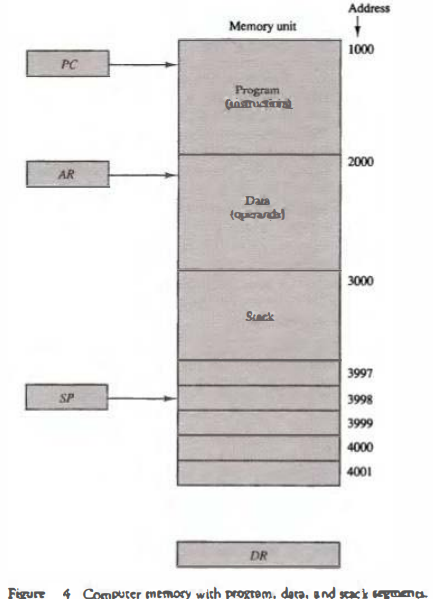
The stack pointer SP points at the top of the stack. The three registers are connected to a common address bus, and either one can provide an address for memory.
PC is used during the fetch phase to read an instruction. AR is used during the execute phase to read an operand.
SP is used to push or pop items into or the stack. As shown in Fig. 4, the initial value of SP is 4001 and the stack grows with decreasing addresses.
Thus the first item stored in the stack is at address 4000, the second item is stored at address 3999, and the last address that can be used for the stack Is 3000.
No provisions are available for stack limjt checks.
We assume that the items in the stack communicate with a data register DR . A new item is inserted with the push operation as follows:
SP ← SP - 1
M[SP] ← DR
The stack pointer is decremented so that it points at the address of the next word. A memory write operation inserts the word from DR into the top of the stack. A new item is deleted with a pop operation as follows:
DR ← M[SP]
SP ← SP + 1
The top item is read from the stack into DR. The stack pointer is then incremented to point at the next item in the stack.
Most computers do not provide hardware to check for stack overflow (full stack) or underflow (empty stack).
The stack limits can be checked by using two processor registers: one to hold the upper limit (3000 in this case), and the other to hold the lower limit (4001 in this case).
After a push operation, SP is compared with the upper-limit register and after a pop operation, SP is compared with the lower-limit register.
The two microoperations needed for either the push or pop are (1) an access to memory through SP, and (2) updating SP. Which of the two microoperations is done first and whether SP is updated by incrementing or decrementing depends on the organization of the stack.
In Fig. 4 the stack grows by decreasing the memory address. The stack may be constructed to grow by increasing the memory address as in Fig. 3.
In such a case, SP is incremented for the push operation and decremented for the pop operation. A stack may be constructed so that SP points at the next empty location above the top of the stack.
In this case the sequence of microoperations must be interchanged. A stack pointer is loaded with an initial value. This initial value must be the bottom address of an assigned stack in memory. Henceforth, SP is automatically decremented or incremented with every push or pop operation.
The advantage of a memory stack is that the CPU can refer to it without having to specify an address, since the address is always available and automatically updated in the stack pointer.
Instruction Formats
A computer will usually have a variety of instruction code formats. It is the function of the control unit within the CPU to interpret each instruction code and provide the necessary control functions needed to process the instruction.
The format of an instruction is usually depicted in a rectangular box symbolizing the bits of the instruction as they appear in memory words or in a control register. The bits of the instruction are divided into groups called fields. The most common fields found in instruction formats are:
1. An operation code field that specifies the operation to be performed.
2. An address field that designates a memory address or a processor
register.
3. A mode field that specifies the way the operand or the effective address
is determined.
Other special fields are sometimes employed under certain circumstances, as for example a field that gives the number of shifts in a shift-type instruction. The operation code field of an instruction is a group of bits that define various processor operations, such as add, subtract, complement, and shift.
The bits that define the mode field of an instruction code specify a variety of alternatives for choosing the operands from the given address.
Operations specified by computer instructions are executed on some data stored in memory or processor registers. Operands residing in memory are specified by their memory address. Operands residing in processor registers are specified with a register address.
A register address is a binary number of k bits that defines one of '2k' registers in the CPU. Thus a CPU with 16 processor registers R0 through R15 will have a register address field of four bits.
The binary number 0101, for example, will designate register RS. Computers may have instructions of several different lengths containing varying number of addresses. The number of address fields in the instruction format of a computer depends on the internal organization of its registers. Most computers fall into one of three types of CPU organizations:
1. Single accumulator organization.
2. General register organization.
3. Stack organization.
In an accumulator-type organization all operations are performed with an implied accumulator register. The instruction format in this type of computer uses one address field.
For example, the instruction that specifies an arithmetic addition is defined by an assembly language instruction as ADD X where X is the address of the operand. The ADD instruction in this case results in the operation AC ← AC + M [X].
AC is the accumulator register and M [X] symbolizes the memory word located at address X.
In a general register type of organization the instruction format in this type of computer needs three register address fields.
Thus the instruction for an arithmetic addition may be written in an assembly language as ADD R1 , R2 , R3 to denote the operation R1 ← R2 + R3.
The number of address fields in the instruction can be reduced from three to two if the destination register is the same as one of the source registers.
Thus the instruction ADD R1 , R2 would denote the operation R1 ← R1 + R2. Only register addresses for R1 and R2 need be specified in this instruction.
Computers with multiple processor registers use the move instruction with a mnemonic MOV to symbolize a transfer instruction. Thus the instruction MOV R1 , R2 denotes the transfer R1 ← R2 (or R2 ← R1, depending on the particular computer).
Thus transfer-type instructions need two address fields to specify the source and the destination.
General register-type computers employ two or three address fields in
Three-Address Instructions
Computers with three-address instruction formats can use each address field to specify either a processor register or a memory operand. The program in assembly language that evaluates X = (A + B) * (C + D) is shown below, together with comments that explain the register transfer operation of each instruction.
ADD R1, A, B  R1 ← M[A] + M[B]
ADD R2, C, D  R2 ← M[C] + M[D]
MOL X, R1, R2  M[X] ← R1 * R2
It is assumed that the computer has two processor registers, R1 and R2. The symbol M[A] denotes the operand at memory address symbolized by A.
The advantage of the three-address format is that it results in short programs when evaluating arithmetic expressions.
The disadvantage is that the binary-coded instructions require too many bits to specify three addresses.
Two-Address Instructions
Two-address instructions are the most common in commercial computers. Here again each address field can specify either a processor register or a memory word. The program to evaluate X = (A + B) * (C + D) is as follows:
MOV R1, A   R1 ← M[A]
ADD R1, B   R1 ← R1 + M[B]
MOV R2, C   R2 ← M[C]
ADD R2, D   R2 ← R2 + M[D]
MOL R1, R2  R1 ← R1 * R2
MOV X, R1   M[X] ← R1
The MOV instruction moves or transfers the operands to and from memory and processor registers.
The first symbol listed in an instruction is assumed to be both a source and the destination where the result of the operation is transferred.
One-Address Instructions
One-address instructions use an implied accumulator (AC) register for all data manipulation. For multiplication and division there is a need for a second register. However, here we will neglect the second register and assume that the AC contains the result of all operations.
The program to evaluate X = (A + B) * (C + D) is
LOAD A  AC ← M[AJ
ADD B   AC ← AC + M[B]
STORE T  M[T] ← AC
LOAD  c  AC ← M[C]
ADD  D   AC ← AC + M[D]
MOL  T   AC ← AC*M[T]
STORE  X  M[X] ← AC
All operations are done between the AC register and a memory operand. T is the address of a temporary memory location required for storing the intermediate result.
Zero-Address Instructions
A stack-organized computer does not use an address field for the instructions ADD and MUL. The PUSH and POP instructions, however, need an address field to specify the operand that communicates with the stack. The following program shows how X = (A + B) * (C + D) will be written for a stack organized computer. (TOS stands for top of stack.)
PUSH A TOS ← A
PUSH B TOS  ← B
ADD TOS ← (A + B)
PUSH C TOS ← C
PUSH D TOS ← D
ADD TO S ← (C + D)
MOL TOS ← (C + D)*(A + B)
POP X M[X] ← TOS
To evaluate arithmetic expressions in a stack computer, it is necessary to convert the expression into reverse Polish notation. The name "zero-address" is given to this type of computer because of the absence of an address field in the computational instructions.