Overflow
When two numbers with n digits each are added and the sum is a number occupying n + 1 digits, we say that an overflow occurred
Overflow is a problem in digital computers because the number of bits that hold the number is finite and a result that contains n + I bits cannot be accommodated by an a-bit word. For this reason. many computers detect the occurrence of an overflow. and when it occurs, a corresponding flip-flop is set that can then be checked by the user.
The detection of an overflow after the addition of two binary numbers depends on whether the numbers are considered to be signed or unsigned. When two unsigned numbers are added an overflow is detected from the end carry out of the most significant position.
In the case of signed numbers two details are important : the leftmost bit always represents the sign and negative numbers are in 2's-complement form. When two signed numbers are added. the sign bit is treated as part of the number and the end carry does not indicate an overflow
An overflow cannot occur after an addition if one number is positive and the other is negative, since adding a positive number to a negative number produces a result whose magnitude is smaller than the larger of the two original numbers.
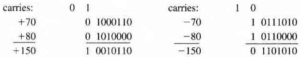
The range of numbers that eight bit registers can accommodate is from binary + 127 to binary - 128.
In the above figure, the eightth bit is sign bit which is 0 for positive numbers and 1 for negative numbers. So when the sum is out of the range of +127 to -128 it causes an overflow.
Note that the eight-bit result that should have been positive has a negative sign bit (i.e the 8-th bit) in the first addition and the eight-bit result that should have been negative has a positive sign bit in the second addition.
If, however, the carry out of the sign bit position is taken as the sign bit of the result then the nine-bit answer so obtained will be correct. But since the answer cannot be accommodated within eight bits, we say that an overflow has occurred.
An overflow condition can be detected by observing the carry into the sign bit position and the carry out of the sign bit position. If these two carries are not equal an overflow has occurred.
In the Binary adder subtractor circuit shownhere. If the two binary numbers are considered to be unsigned then the C bit detects a carry after addition or a borrow after subtraction.
If the numbers are considered to be signed, then the V bit detects an overflow. If V = 0 after an addition or subtraction then no overflow occurred and the n bit result is correct.
If V = 1 then the result of the operation contains n + 1 bits, but only the rightmost n bits of the number fit in the space available, so an overflow has occurred. The (n + 1)th bit is the actual sign and has been shifted out of position.
BCD ADDER
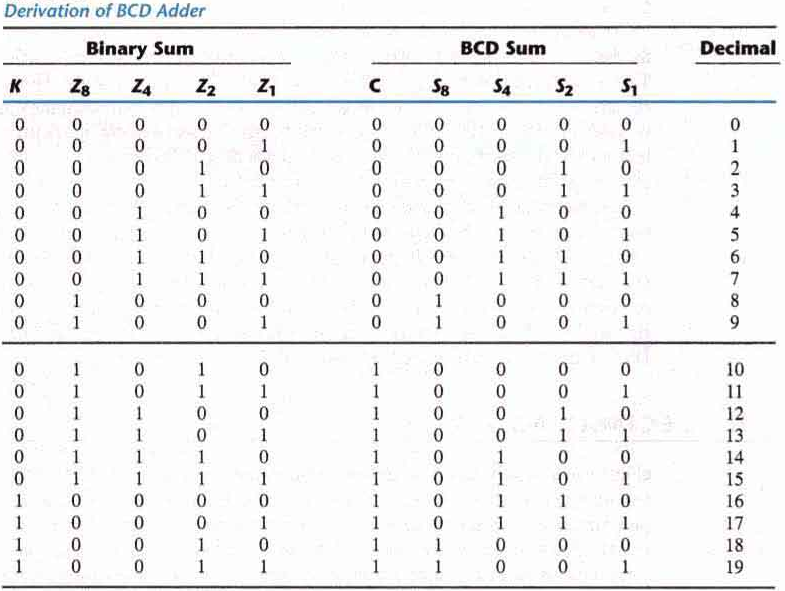
The table shows the BCD representation of binary digits.
In examining the contents of the table, it becomes apparent that when the binary sum is equal to or less than 1001, the corresponding BCD number is identical and therefore no conversion is needed
When the binary sum is greater than 1001, we obtain an invalid BCD representation. The addition of binary 6 (0110) to the binary sum converts it to the correct BCD representation and also produces an output carry as required.
The logic circuit that detects the necessary correction can be derived from the entries in the table above. It is obvious that a correction is needed when the binary sum has an output carry K = 1.
The other six combinations from 1010 through 1111 that need a correction have a 1 in position Z8. To distinguish them from binary 1000 and 1001, which also have a 1 in position Z8, we specify further that either Z4 Or Z2 must have a 1.
The condition for a correction and an output carry can be expressed by the Boolean function C = K + Z8 . Z4 + Z8 . Z2
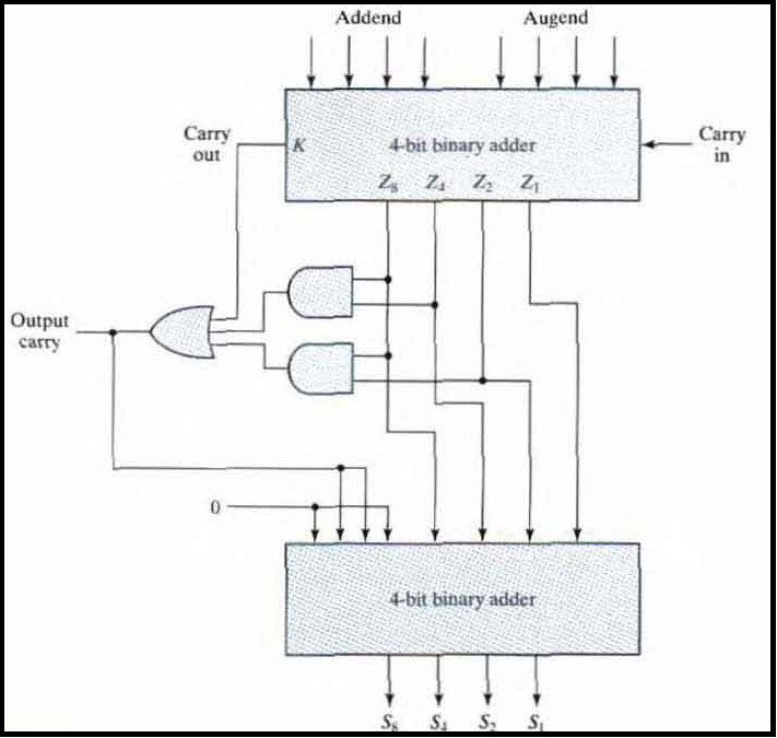
When C = 1, it is necessary to add 0110 to the binary sum and provide an output carry for the next stage. A BCD adder that adds two BCD digits and produces a sum digit in BCD is shown above.
The two decimal digits togethar with the input carry are first added in the top four-bit adder to produce the binary sum. When the output carry is equal to 0 nothing is added to the binary sum.
When it is equal to 1 binary 0110 is added to the binary sum through the bottom four-bit adder. The output carry generated from the bottom adder can be ignored since it supplies information already available at the output carry terminal.
A decimal parallel adder that adds 'n' decimal digits needs 'n' BCD adder stages. The output carry from one stage must be connected to the input carry of the next higher order stage.
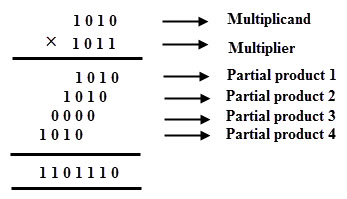
BINARY MULTIPLIER
Assume The multiplicand bits are B1 and B0, the multiplier bits are A1 and A0 and the product is C3C2C1C0
The first partial product is formed by multiplying B1B0 by A0. The multiplication of two bits such as A0 and B0 produces a 1 if both bits are 1 and otherwise it produces a 0. This is identical to an AND operation. Therefore, the partial product can be implemented with AND gates as shown in the diagram. The second partial product is formed by multiplying B1B0 by A1 and shifting the result by one position to the left. The two partial products are added with two half-adder (HA) circuits.
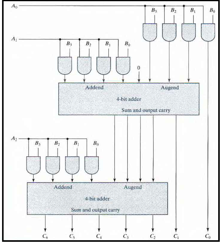
Usually, there are more bits in the partial products and it is necessary to use full adders to produce the sum of the partial products.
A combinational circuit binary multiplier with more bits can be constructed in a similar fashion. A bit of the multiplier is ANDed with each bit of the multiplicand in as many levels as there are bits in the multiplier
The binary output in each level of AND gates is added with the partial product of the previous level to form a new partial product. The last level produces the product. For 'J' multiplier bits and K multiplicand bits. we need (J X K) AND gates and ( J - 1) K-bit adders to produce a product of J + K bits.
MAGNITUDE COMPARATOR
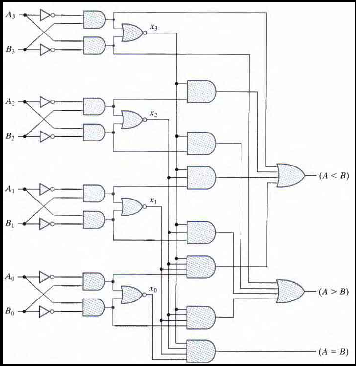
The comparison of two numbers is an operation that determines whether one number is greater than, less than, or equal to the other number. A magnitude comparator is a combinational circuit that compares two numbers A and B and determines their relative magnitudes
The outcome of the comparison is specified by three binary variables that indicate whether A < B, A = B, or A > B.
The circuit for comparing two n-bit numbers has 22n entries in the truth table and becomes too cumbersome even with n = 3
An algorithm for the design of a four-bit magnitude comparator is shown in the below steps: Consider two numbers. A and B with four digits each. Write the coefficients of the numbers in descending order of significance: A3A2A1A0 and B3B2B1B0
The two numbers are equal if all pairs of significant digits are equal i.e. A3 = B3 and A2 = B2 and A1 = B1 and A0 = B0. When the numbers are binary the digits are either 1 or 0 and the equality of each pair of bits can be expressed logically with an exclusive-NOR function as: xi = AiBi + A'iB'i for i = 0, 1, 2, 3... where xi = 1 only if both bits are equal.
For both the binary numbers to be equal all xi for i = 0, 1, 2, 3... should be 1. This can be shown using the expression: (A=B) = x3x2x1x0
The pin (A=B) will be 1 only if all xi are 1.
To determine whether A is greater or less than B we check the corresponding bits of A and B from MSB to LSB. If at any level we find A = 0 and B = 1 we say A < B or in reverse case A > B.
This can be shown using boolean algebra:
( A > B) = A3B'3 + x3A2B'2 + x3x2A1B'1 + x3x2x1A0B'0
( A < B) = A'3B3 + x3A'2B2 + x3x2A'1B'1 + x3x2x1A'0B'0
The symbols (A > B ) and ( A < B) are binary output variables that are equal to 1 when A > B and A < B. respectively.