DECODERS
Discrete quantities of information are represented in digital systems by binary codes. A binary code of 'n' bits is capable of representing up to 2n distinct elements of coded information.
A decoder is a combinational circuit that converts binary information from n input lines to a maximum of 2n unique output lines. If the n-bit coded information has unused combination the decoder may have fewer than 2n outputs.
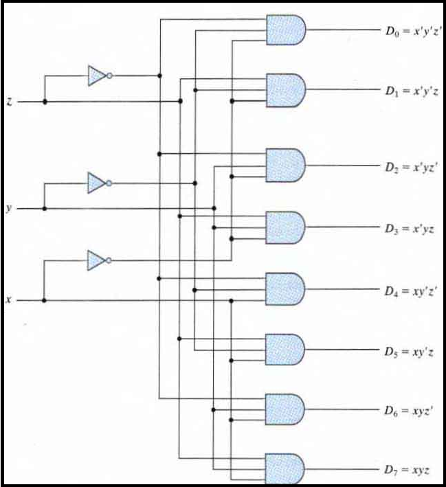
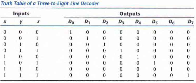
Example (three to Eight line Decoder): The three inputs are decoded into eight outputs each representing one of the minterms of the three input variables. The three inverters provide the complement of the inputs, and each one of the eight AND gates generates one of the minterms. This is used in binary to octal conversions
The input variables represent a binary number and the outputs represent the eight digits of a number in the octal number system. However, a three-to-eight-line decoder can be used for decoding any three-bit code to provide eight outputs, one for each element of the code.
Logical circuit of a 3:8 encoder :
Two to Four line decoder with enable input
Decoders include one or more enable inputs to control the circuit operation. The decoder is enabled when E is equal to 0 (i.e. active-low enable).
The Output whose value is equal to 0 represents the minterm selected by inputs A and B. The circuit is disabled when E is equal to 1 regardless of the values of the other two inputs. When the circuit is disabled none of the outputs are equal to and none of the minterms are selected.
A decoder with enable input can function as a demultiplexer - a circuit that receives information from a single line and directs it to one of the 2n possible output lines.
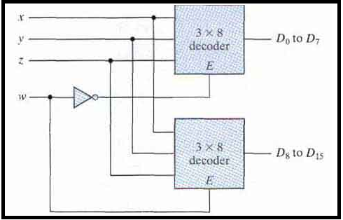
Decoders with enable inputs can be connected together to form a larger decoder circuit. So two 3-8 line decoders with enable inputs connected to form a 4-to-16 line decoder.
When w = 0 the top decoder is enabled and the other is disabled. The bottom decoder outputs are all 0's and the top eight outputs generate minterms 0000 to 0111.
When w = 1, the enable conditions are reversed: The bottom decoder outputs generate minterms 1000 to 1111, while the outputs of the top decoder are all 0's.
Thus, enable inputs are a convenient feature for interconnecting two or more standard components for the purpose of combining them into a similar function with more inputs and outputs.
Combinational logic Implementation
A decoder that generates the - minterms of the function together with an external OR gate that forms their logical sum provide a hardware implementation of the function.
In this way any combinational circuit with 'n' inputs and 'm' outputs can be implemented with an n-to-2n line decoder and 'm' OR gates.
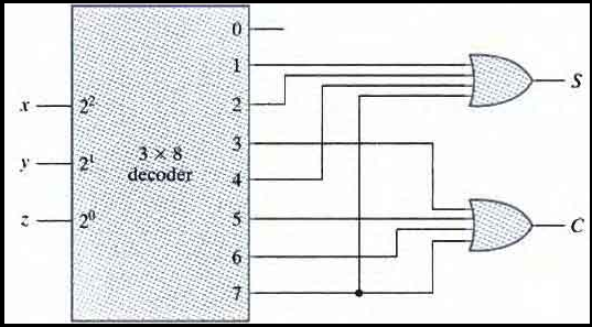
This procedure to obtain any combinational circuit from a decoder is illustrated by an example that implements a full-adder circuit.
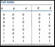
The truth table for full adder is below:
Since there are three inputs and a total of eight minterms, we need a three-to-eight-line decoder. The decoder generates the eight minterms for x, y, and z. The OR gate for output 'S' forms the logical sum of minterms 1, 2, 4, 7. The OR gate for output 'C' forms the logical sum of mime rms 3, 5, 6 and 7.
Minterms representing S and C are
S(x, y, z) = ∑(1, 2, 4, 7)
C(x, y, z) = ∑(3, 5, 6, 7)
A function with a long list of minterms requires an OR gate- with a large number of inputs. A function having a list of k minterms can be expressed in its complemented form F' with 2n - k minterms.
ENCODERS
An encoder is a digital circuit that performs the inverse operation of a decoder. An encoder has 2n (or fewer) input lines and 'n' output lines.
The output lines as an aggregate generate the binary code corresponding to the input value.
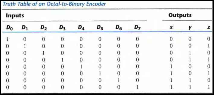
Example: Octal to Binary encoder (8-3 encoder)
It has eight inputs (one for each of the octal digits) and three outputs that generate the corresponding binary number. It is assumed that only one input has a value of 1 at any given time.
The encoder can be implemented with OR gates whose inputs are determined directly from the truth table
Output 'z' is equal to 1 when the input octal digit is 1, 3, 5, 7. Output y is 1 for octal digits 2, 3, 6 or 7 and output x is 1 for digits 4, 5, 6 or 7. These conditions can be expressed by the following Boolean output functions:
z = D1 + D3 + D5 + D7
y = D2 + D3 + D6 + D7
x = D4 + D5 + D6 + D7
The encoder defined in Table above has the limitation that only one input can be active at any given time
If two inputs are active simultaneously the output produces an undefined combination. For example, if D3 and D6 are 1 simultaneously the output of the encoder will be 111 because all three outputs are equal to 1. The output 111 does not represent either binary 3 or binary 6.
To resolve this ambiguity, encoder circuits must establish an input priority to ensure that only one input is encoded. If we establish a higher priority for inputs with higher subscript numbers, and if both D3 and D6 are 1 at the same time, the output will be 110 because D6 has higher priority than D3.
Another ambiguity in the octal-to-binary encoder is that an output with all 0's is generated when all the inputs are 0; but this output is the same as when D0 is equal to 1. The discrepancy can be resolved by providing one more output to indicate whether at least one input is equal to 1.
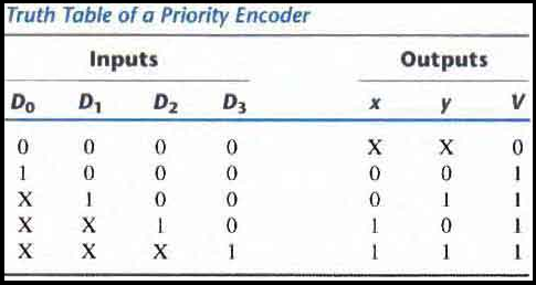
Priority Encoder
A priority encoder is an encoder circuit that includes the priority function. The operation of the priority encoder is such that if two or more inputs are equal to 1 at the same time. The input having the highest priority will take precedence.
In addition to the two outputs x and y the circuit has a third output designated by V: which is a valid bit indicator that is set to 1 when one or more inputs are equal to 1.
If all inputs are 0, there is no valid input and V is equal to 0. The other two outputs are not inspected when v equals 0 and are specified as don't-care conditions.
The higher the subscript number, the higher the priority of the input. Input D3 has the highest priority. So, regardless of the values of the other inputs. When this input is 1 then outputs xy are 11.
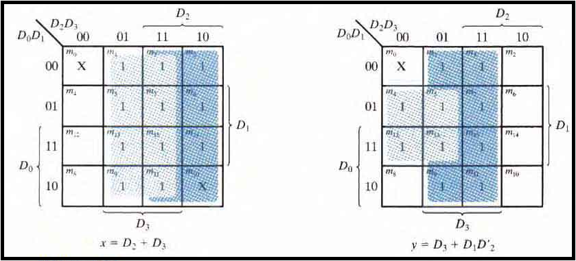
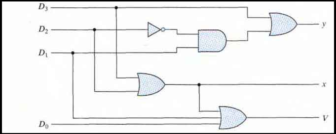
The priority encoder is implemented according to the following Boolean functions:
x = D2 + D3
y = D3 + D1D'2
V = D0 + D1+ D2+ D3
MULTIPLEXERS
A multiplexer is a combinational circuit that selects binary information from one of many input lines and directs it to a single output line.
The selection of a particular input line is controlled by a set of selection lines. Normally, there are 2n input lines and 'n' selection lines whose bit combinations determine which input is selected.
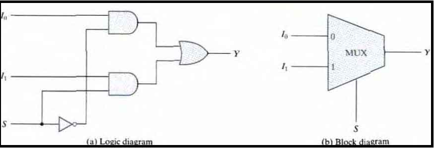
A two-to-one-line multiplexer connects one of two 1-bit sources to a common destination. The circuit has two data input lines, one output line, and one selection line S. When S = 0 the upper AND gate is enabled and I0 has a path to the output. When S = 1, the lower AND gate is enabled and I1 has a path to the output.
A multiplexer acts like a switch that selects one of the two outputs.
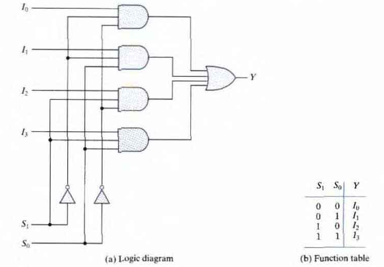
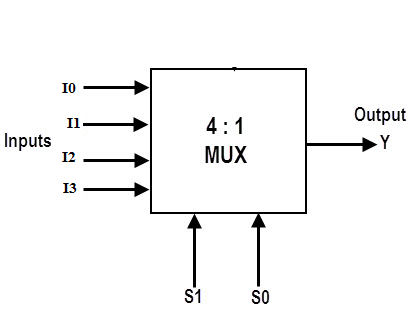
Four-to-one-line multiplexer
Each of the four Inputs I0 through I3 is applied to one input or an AND gate. Selection lines S1 and S0 are decoded to select a particular AND gate.
The outputs of the AND gates are applied to a single OR gate that provides the one-line output
From the diagram suppose if the inputs of the selectors is S1S0 = 10. So the AND gate to which I2 is connected has two inputs 1 and the last input is I2 which means that whatever is the value of I2 is the output of the multiplexer. Since all other AND gates are at 0.
A multiplexer is also called a data selector, since it selects one of many inputs and steers the binary information to the output line.
Implement a Boolean function with Multiplexer
The general procedure for implementing any Boolean function of 'n' variables with a multiplexer with n - 1 selection inputs and 2n - 1 data inputs is as follows:
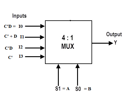
Implement F(A,B,C,D) = ∑ m(1,4,5,7,9,12,13) using 4 * 1 mux
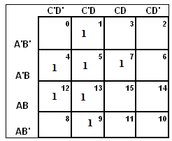
First we need to make a kmap of 4 variables as there are 4 variables. As shown below and fill values of minterms.
Then we have a 4:1 mux and set S0 as B and S1 as A (assumption).
Step 1: We draw the table of S0S1 and output Y. It has two variables and one output.
Step 2: We need to figure out the values of output Y for all cases.
When S1 = 0, S0 = 0 we see the first row of the kmap, we have minterm C'D = 1. So we put I0 = C'D.
When S1 = 0, S0 = 1 we see the second row of the kmap, we have minterms C'D , C'D', CD = 1. So we split the three squares into rectangle of two squares each i.e. (C'D' , C'D = C') and (C'D, CD = D). Hence we get I1 = C' + D.
When S1 = 1, S0 = 0 we see the fourth row of the kmap, we have minterm C'D = 1. So we put I2 = C'D.
When S1 = 1, S0 = 1 we see the third row of the kmap, we have minterm C'D' and C'D = 1. So we put I3 = C'.
Step 3:Complete the mux as shown below
| S1 = A | S0 = B | Y = Output |
|---|---|---|
| 0 | 0 | I0 |
| 0 | 1 | I1 |
| 1 | 0 | I2 |
| 1 | 1 | I3 |
| S1 = A | S0 = B | Y = output |
|---|---|---|
| 0 | 0 | I0 = C'D |
| 0 | 1 | I1 = C' + D |
| 1 | 0 | I2 = C' |
| 1 | 1 | I3 = C'D |