ANALYSIS OF CLOCKED SEQUENTIAL CIRCUITS
Some flip-flops have asynchronous inputs that are used to force the flip-flop to a particular state independently of the clock
The input that sets the flip-flop to 1 is called preset or direct set. The input that clears the flip-flop to 0 is called clear or direct reset.
When power is turned on in a digital system, the state of the flip-flops is unknown. The direct inputs are useful for bringing all flip-flops in the system to a known starting state prior to the clocked operation.
The knowledge of the type of flip-flops and a list of the Boolean expressions of the combinational circuit provide the information needed to draw the logic diagram of the sequential circuit. The part of the combinational circuit that gene rates external outputs is described algebraically by a set of Boolean functions called output equations. The part of the circuit that generates the inputs to flip-flops is described algebraically by a set of Boolean functions called flip-flop input equations (or excitation equations).
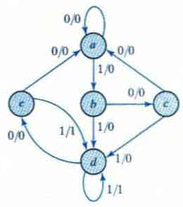
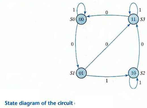
The information available in a state table can be represented graphically in the form of a state diagram. In this type of diagram a state is represented by a circle and the (clock-triggered) transitions between states are indicated by directed lines connecting the circles.
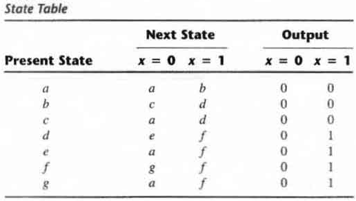
The time sequence of inputs, outputs, and flip-flop states can be enumerated in a state table (transition table). The table has four parts present state, next state, inputs and outputs.
In general a sequential circuit with 'm' flip-flops and 'n' inputs needs 2m+n rows in the state table.
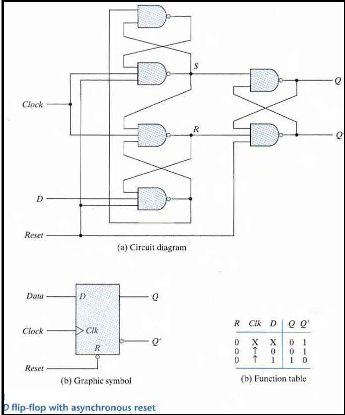
Positive Edge Triggered D Flip-flop
A circuit diagram of a Positive edge triggered D Flip-flop is shown as below. It has an additional reset input connected to the three NAND gates.
When the reset input is 0 it forces output Q' to Stay at 1 which clears output Q to 0 thus resetting the flip-flop.
Two other connections from the reset input ensure that the S input of the third SR latch stays at logic 1 while the reset input is at 0 regardless of the values of D and Clk.
Function table suggests that:
When R = 0, the output is set to 0 (independent of D and Clk).
The clock at Clk is shown with an upward arrow to indicate that the flip-flop triggers on the positive edge of the clock.
The value in D is transferred to Q with every positive-edge clock signal provided that R = 1.
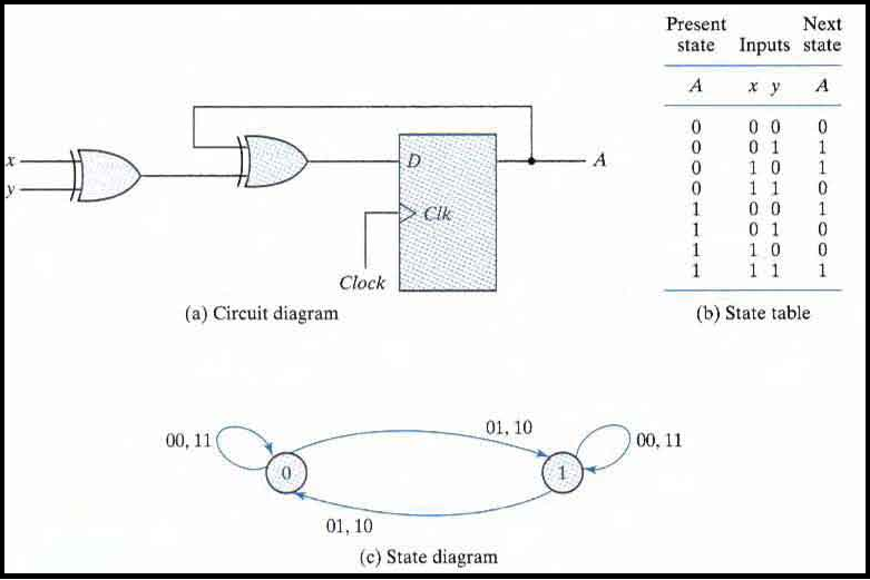
Analysis with D Flip-Flops
The input equation of a D Flip-flop is given by DA = A ⊕ x ⊕ y. DA means a D Flip-flop with output A.
The x and y variables are the inputs to the circuit. No output equations are given, which implies that the output comes from the output of the flip-flop.
The state table has one column for the present state of flip-flop 'A' two columns for the two inputs, and one column for the next state of A.
The next-state values are obtained from the state equation A(t + 1) = A ⊕ x ⊕ y.
The expression specifies an odd function and is equal to 1 when only one variable is 1 or when all three variables are 1.
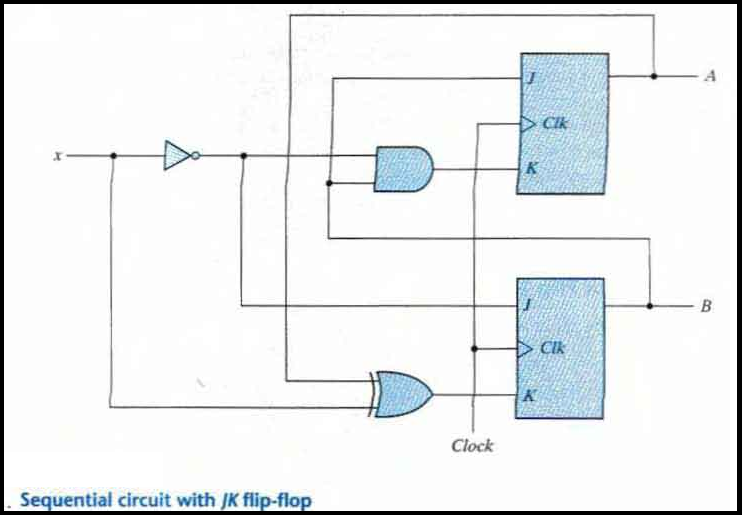
Analysis with JK Flip-Flops
The circuit can be specified by the flip-flop input equations:
JA = B; KA = Bx'
JB = x'; KB = A'x + Ax' = A ⊕ x
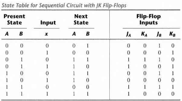
The next state of each flip-flop is evaluated from the corresponding J and K inputs and the characteristic table of the JK flip-flop listed as:
When J = 1 and K = 0 the next state is 1
When J = 0 and K = 1 the next state is 0
When J = 0 and K = 0 there is no change of state and the next-state value is the same as that of the present state.
When J = K = 1, the next-state bit is the complement of the present-state bit.
The characteristic equations for the flip-flops are
A(t + 1) = JA' + K'A
B(t + 1) = JB' + K'B
This gives us the state equation of A by substituting the values of JA, KA
A(t + 1) = BA' + (Bx')'A = A'B + AB' + Ax
The state equation provides the bit values for the column headed "Next State" for A in the state table. Similarly, the state equation for flip-flop B can be derived from the characteristic equation by substituting the values of JB and KB.:
B(t + 1) = x'B' + (A ⊕ x)'B = B'x' + ABx + A'Bx'
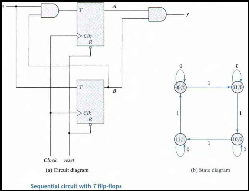
Analysis with T Flip-Flops
The circuit can be specified by the characteristic equations:
Q(t+1) = T ⊕ Q = T'Q + TQ'
The sequential circuit has two flip-flops A and B, one input x, and one output y and can be described algebraically by two input equations and an output equation:
TA = Bx
TB = x
y = AB
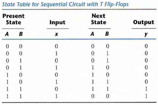
The state table for the circuit is listed below. The values for y are obtained from the output equation. The values for the next state can be derived from the state equations by substituting TA and TB in the characteristic equations yielding:
A(t + 1) = (Bx)' A + (Bx)A' = AB' + Ax' + A'Bx
B(t + 1) = x ⊕ B
STATE REDUCTION AND ASSIGNMENT
Two sequential circuits may exhibit the same input-output behavior but have a different number of internal states in their state diagram.
Certain properties of sequential circuits may simplify a design by reducing the number of gates and flip-flops it uses. Reducing the number of flip-flops reduces the cost of a circuit.
The reduction in the number of flip-flops in a sequential circuit is referred to as the state reduction problem. State-reduction algorithms are concerned with procedures for reducing the number of states in a state table while keeping the external input-output requirements unchanged
Example of State Reduction
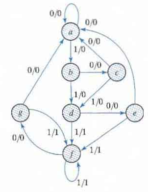
First we need the state table: it is more convenient to apply procedures for state reduction with the use of a table rather than a diagram.
Then we apply the reduction algorithms "Two states are said to be equivalent if for each member of the set of inputs they give exactly the same output and send the circuit either to the same state or to an equivalent state."
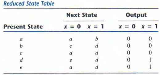
When two states are equivalent one of them can be removed without altering the input-output relationships.
Going through the state table, we look for two present states that go to the same next state and have the same output for both input combinations. States g and e are two such states.
The procedure of removing a state and replacing it by its equivalent is "The row with present state g is removed and state g is replaced by state e each time it occurs in the columns headed "Next State,"
Similarly, states f and d are equivalent, and state f can be removed and replaced by d.
In general reducing the number of states in a state table may result in a circuit with less equipents. But it does not guarantee a saving in the number of flip-flops or the number of gates.