SYNCHRONOUS COUNTERS
Synchronous counters are different from ripple counters in that clock pulses are applied to the inputs of all flip-flops. A common clock triggers all flip-flops simultaneously rather than one at a time in succession as in a ripple counter. In synchronous counters, the clock inputs of all the flip-flops are connected together and are triggered by the input pulses. Thus, all the flip-flops change state simultaneously (in parallel)
Binary Counter
In a synchronous binary counter the flip-flop in the least significant position is complemented with every pulse.
A flip-flop in any other position is complemented when all the bits in the lower significant positions are equal to 1.
If the present state of a four-bit counter is A3A2A1A0 = 0011 the next count is 0100. A0 is always complemented. A1 is complemented because the present state of A0 = 1. A2 is complemted because the present State of A1A0 = 11. However A3 is not complemented because the present state of A2A1A0 = 011 which does not give an all 1's condition.
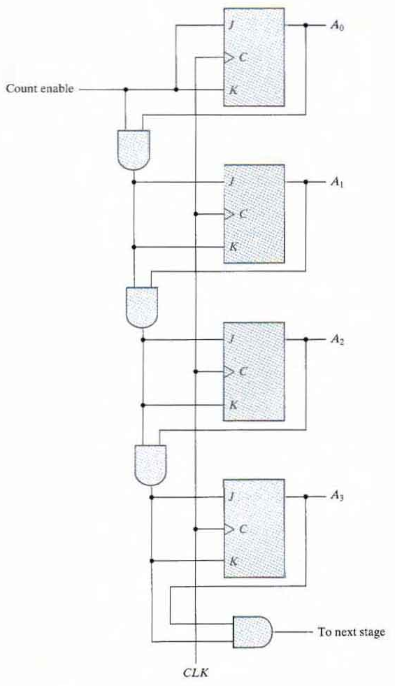
Four-bit synchronous binary counter
Synchronous binary counters have a regular pattern and can be constructed with complementing flip-flops and gates.
The C inputs of all flip-flops are connected to a common clock. The counter is enabled with the count enable input.
If the enable input is 0 all J and K inputs are equal to 0 and the clock does not change the state of the counter.
The first stage A0 has its J and K equal to 1 if the counter is enabled.
The other J and K inputs are equal to 1 if all previous least significant stages are equal to 1 and the count is enabled.
The chain of AND gates generates the required logic for the J and K inputs in each stage. The counter can be extended to any number of stages with each stage having an additional flip-flop and an AND gate that gives an output of 1 if all previous flip-flop outputs are 1.
Ring Counter
Timing signals that control the sequence of operations in a digital system can be generated by a shift register or by a counter with a decoder.
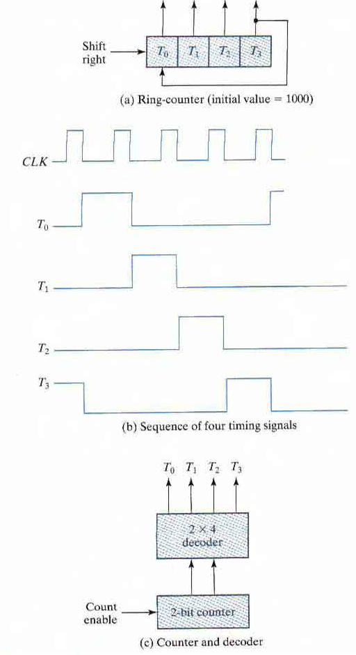
A ring counter is a circular shift register with only one flip-flop being set at any particular time; all others are cleared. The single bit is shifted from one flip-flop to the next to produce the sequence of timing signals.
The initial value of the register is 1000 and requires Preset/Clear flip-flops. The single bit is shifted right with every clock pulse and circulates back from T3 to T0.
Each flip-flop is in the 1 state once every four clock cycles and produces one of the four timing signals. Each output becomes a 1 after the negative-edge transition of a clock pulse and remains 1 during the next clock cycle.
To generate 2n timing signals we need either a shift register with 2n flip-flops or an 'n' bit binary counter together with a n-to-2n line decoder.
For example, 16 timing signals can be generated with a l6-bit shift register connected as a ring counter or with a 4-bit binary counter and a 4-to-l6 line decoder. In the first case we need 16 flip-flops. In the second, we need 4 flip-flops and 16 four input AND gates for the decoder.
Block diagram of ring counter :
Truth Table of ring counter :
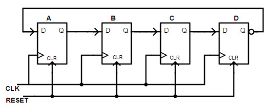
| Q0 | Q1 | Q2 | Q4 |
|---|---|---|---|
| 1 | 0 | 0 | 0 |
| 0 | 1 | 0 | 0 |
| 0 | 0 | 1 | 0 |
| 0 | 0 | 0 | 1 |
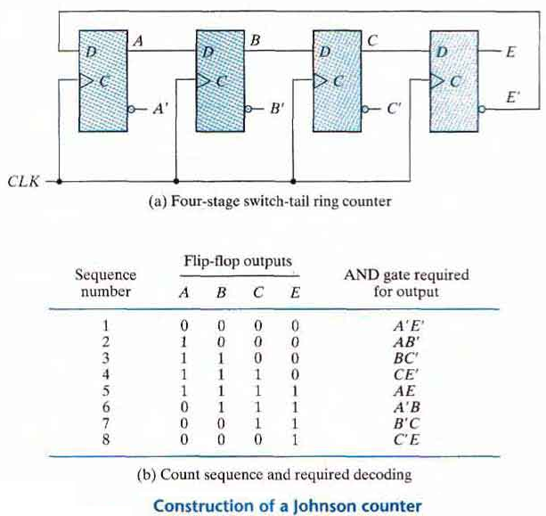
Johnson Counter
A k-bit ring counter circulates a single bit among the flip-flops to provide k distinguishable states. The number of states can be doubled if the shift register is connected as a switch-tail ring counter.
A switch-tail ring counter is a circular shift register with the complemented output of the last flip-flop connected to the input of the first flip-flop
The circular connection is made from the complemented output of the rightmost flip-flop to the input of the leftmost flip-flop. The register shifts its contents once to the right with every clock pulse and at the same rime, the complemented value of the E flip-flop is transferred into the A flip-flop.
Starting from a cleared state the switch-tail ring counter goes through a sequence of eight states, as listed in above table.
In general, a k-bit switch-tail ring counter will go through a sequence of 2k states.
Starting from all 0's, each shift operation inserts 1's from the left until the register is filled with all 1's.
In the next sequences, 0's are inserted from the left until the register is again filled with all 0's.
A Johnson counter is a k-bit switch-tail ring counter with 2k decoding gates to provide out puts for 2k timing signals.
One disadvantage of the circuit shown above is that if it finds itself in an unused state, it will persist in moving from one invalid state to another and never find its way to a valid state.
Johnson counters can be constructed for any number of timing sequences. The number of flip-flops needed is one-half the number of timing signals.
The number of decoding gates is equal to the number of timing signals and only two-input gates are needed.