Network Models
A network is a combination of hardware and software that sends data from one location to another. The hardware consists of the physical equipment that carries signals from one point of the network to another. The software consists of instruction sets that make possible the services that we expect from a network.
The layered model that dominated data communications and networking literature before 1990 was the Open Systems Interconnection (OSI) model. Everyone believed that the OSI model would become the ultimate standard for data communications, but this did not happen.
The TCP/IP protocol suite became the dominant commercial architecture because it was used and tested extensively in the Internet; the OSI model was never fully implemented.
THE OSI MODEL
An ISO standard that covers all aspects of network communications is the Open Systems Interconnection model.
An open system is a set of protocols that allows any two different systems to communicate regardless of their underlying archi- tecture.
The purpose of the OSI model is to show how to facilitate communication between different systems without requiring changes to the logic of the underlying hardware and software.
The OSI model is not a protocol; it is a model for understanding and designing a network architecture that is flexible, robust, and interoperable.
It consists of seven separate but related layers, each of which defines a part of the process of moving information across a network
Layered Architecture :
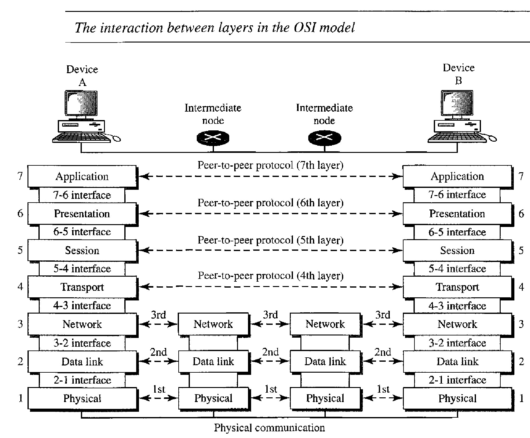
As the message travels from A to B, it may pass through many intermediate nodes. These intermediate nodes usually involve only the first three layers of the OSI model.
In developing the model, the designers distilled the process of transmitting data to its most fundamental elements. They identified which networking functions had related uses and collected those functions into discrete groups that became the layers.
Each layer defines a family of functions distinct from those of the other layers.
Within a single machine, each layer calls upon the services of the layer just below it. Layer 3, for example, uses the services provided by layer 2 and provides services for layer 4.
Between machines, layer x on one machine communicates with layer x on another machine. This communication is governed by an agreed-upon series of rules and conventions called protocols. The processes on each machine that communicate at a given layer are called peer-to-peer processes.
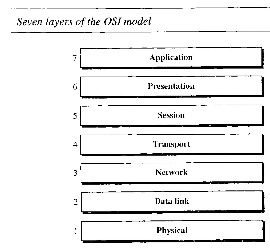
Open System Interconnect Layers
At the physical layer, communication is direct. At the higher layers, however, communication must move down through the layers on device A, over to device B, and then back up through the layers.
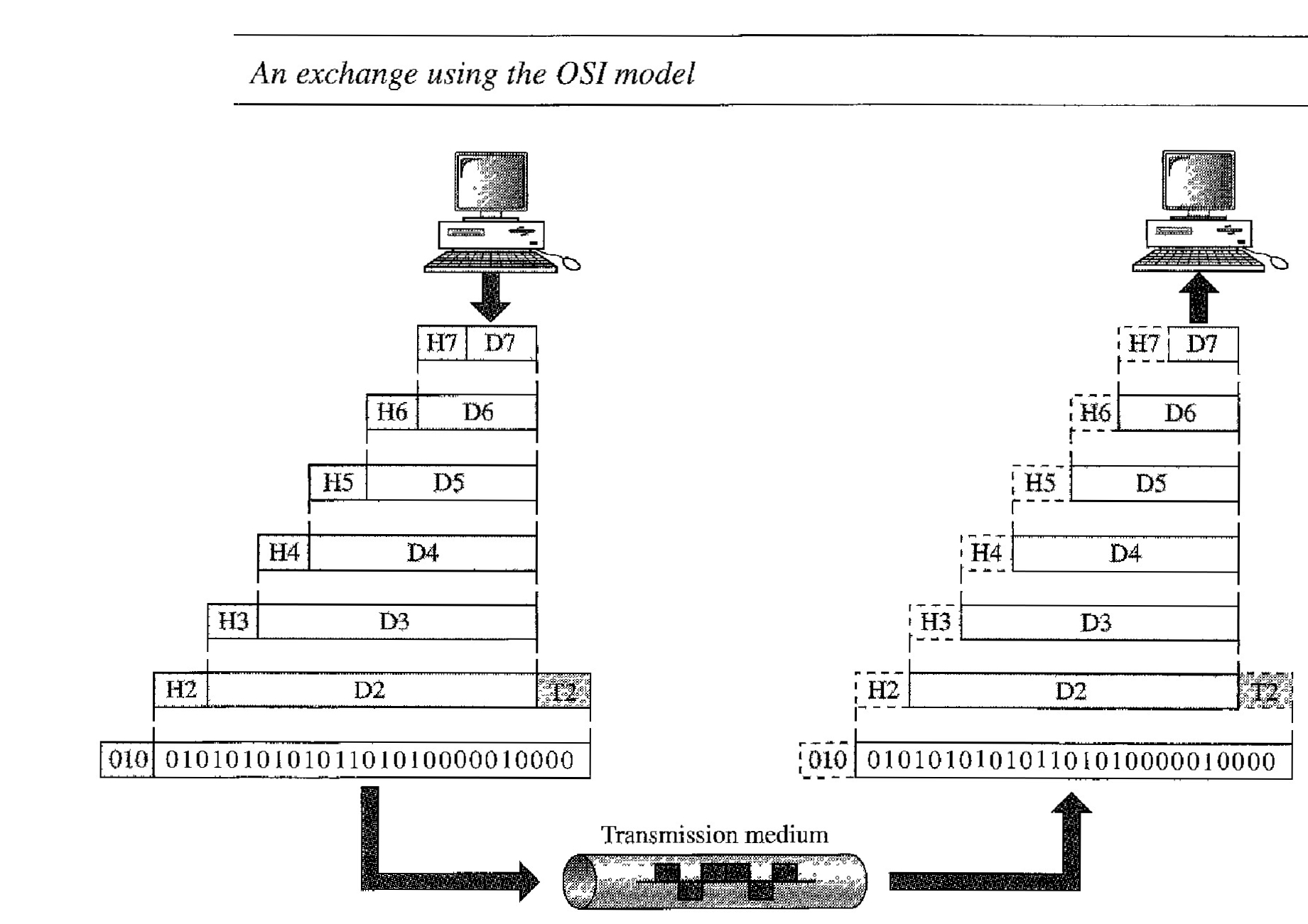
Each layer in the sending device adds its own information to the message it receives from the layer just above it and passes the whole package to the layer just below it.
At layer I the entire package is converted to a form that can be transmitted to the receiving device. At the receiving machine, the message is unwrapped layer by layer, with each process receiving and removing the data meant for it. For example, layer 2 removes the data meant for it, then passes the rest to layer 3. Layer 3 then removes the data meant for it and passes the rest to layer 4, and so on.
The passing of the data and network information down through the layers of the send- ing device and back up through the layers of the receiving device is made possible by an interface between each pair of adjacent layers.
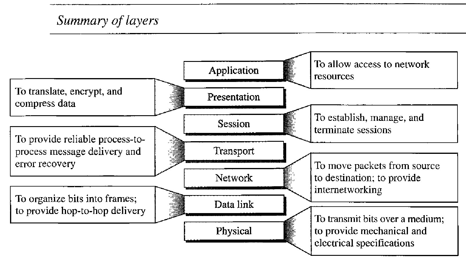
The seven layers can be thought of as belonging to three subgroups.
Layers l, 2, and 3 - physical, data link, and network-are the network support layers; They deal with the physical aspects of moving data from one device to another (such as electrical specifications, physical connections, physical addressing, and transport timing and reliability).
Layer 4, the transport layer, links the two subgroups and ensures that what the lower layers have transmitted is in a form that the upper layers can use.
Layers 5, 6, and 7-session, presentation, and application - can be thought of as the user support layers; they allow interoperability among unrelated software systems.
The upper OSI layers are almost always implemented in software; lower layers are a combination of hardware and software, except for the physical layer, which is mostly hardware.
At each layer, a header, or possibly a trailer, can be added to the data unit. Commonly, the trailer is added only at layer 2. When the formatted data unit passes through the physical layer (layer 1), it is changed into an electromagnetic signal and transported along a physical link.
Upon reaching its destination as each block of data reaches the next higher layer, the headers and trailers attached to it at the corresponding sending layer are removed, and actions appropriate to that layer are taken. By the time it reaches layer 7, the message is again in a form appropriate to the application and is made available to the recipient.
A packet (header and data) at level 7 is encapsulated in a packet at level 6. The whole packet at level 6 is encapsulated in a packet at level 5, and so on. In other words, the data portion of a packet at level N - 1 carries the whole packet (data and header and maybe trailer) from level N. The concept is called encapsulation; level N - 1 is not aware of which part of the encapsulated packet is data and which part is the header or trailer. For level N - 1, the whole packet coming from level N is treated as one integral unit.
LAYERS IN THE OSI MODEL
Physical Layer :
The physical layer coordinates the functions required to carry a bit stream over a physical medium. It deals with the mechanical and electrical specifications of the interface and transmission medium. It also defines the procedures and functions that physical devices and interfaces have to perform for transmission to occur.
The physical layer defines the characteristics of the interface between the devices and the transmission medium. It also defines the type of transmission medium.
The physical layer data consists of a stream of bits (sequence of 0s or 1s) with no interpretation. To be transmitted, bits must be encoded into signals - electrical or optical. The physical layer defines the type of encoding (how Osand Is are changed to signals).
The transmission rate-the number of bits sent each second-is also defined by the physical layer. In other words, the physical layer defines the dura- tion of a bit, which is how long it lasts
The sender and receiver not only must use the same bit rate but also must be synchronized at the bit level. In other words, the sender and the receiver clocks must be synchronized.
The physical layer is concerned with the connection of devices to the media. In a point-to-point configuration, two devices are connected through a dedicated link. In a multipoint configuration, a link is shared among several devices.
The physical topology defines topology i.e. how devices are connected to make a network. The physical layer also defines the direction of transmission between two devices: simplex, half-duplex, or full-duplex.
Data Link Layer :
The data link layer transforms the physical layer, a raw transmission facility, to a reliable link. It makes the physical layer appear error-free to the upper layer (network layer). he data link layer is responsible for moving frames from one hop (node) to the next.
The data link layer divides the stream of bits received from the network layer into manageable data units called frames.
If frames are to be distributed to different systems on the network, the data link layer adds a header to the frame to define the sender and/or receiver of the frame. If the frame is intended for a system outside the sender's network, the receiver address is the address of the device that connects the network to the next one.
If the rate at which the data are absorbed by the receiver is less than the rate at which data are produced in the sender, the data link layer imposes a flow control mechanism to avoid overwhelming the receiver.
The data link layer adds reliability to the physical layer by adding mechanisms to detect and retransmit damaged or lost frames. It also uses a mechanism to recognize duplicate frames. Error control is normally achieved through a trailer added to the end of the frame.
When two or more devices are connected to the same link, data link layer protocols are necessary to determine which device has control over the link at any given time.
Network Layer : The network layer is responsible for the delivery of individual packets from the source host to the destination host.
The network layer is responsible for the source-to-destination delivery of a packet, possibly across multiple networks (links). Whereas the data link layer oversees the delivery of the packet between two systems on the same network (links), the network layer ensures that each packet gets from its point of origin to its final destination.
If two systems are connected to the same link, there is usually no need for a network layer. However, if the two systems are attached to different networks (links) with connecting devices between the networks (links), there is often a need for the network layer to accomplish source-to-destination delivery.
The physical addressing implemented by the data link layer handles the addressing problem locally. If a packet passes the network boundary, we need another addressing system to help distinguish the source and destination systems. The network layer adds a header to the packet coming from the upper layer that, among other things, includes the logical addresses of the sender and receiver.
When independent networks or links are connected to create internetworks (network of networks) or a large network, the connecting devices (called routers or switches) route or switch the packets to their final destination. One of the functions of the network layer is to provide this mechanism.
Transport Layer : The transport layer is responsible for the delivery of a message from one process to another.
Computers often run several programs at the same time. For this reason, source-to-destination delivery means delivery not only from one computer to the next but also from a specific process (running program) on one computer to a specific process (running program) on the other. The transport layer header must therefore include a type of address called a service-point address (or port address). The network layer gets each packet to the correct computer; the transport layer gets the entire message to the correct process on that computer.
A message is divided into transmittable segments, with each segment containing a sequence number. These numbers enable the transport layer to reassemble the message correctly upon arriving at the destination and to identify and replace packets that were lost in transmission.
The transport layer can be either connectionless or connection oriented. A connectionless transport layer treats each segment as an independent packet and delivers it to the transport layer at the destination machine. A connection oriented transport layer makes a connection with the transport layer at the destination machine first before delivering the packets. After all the data are transferred, the connection is terminated
Like the data link layer, the transport layer is responsible for flow control. However, flow control at this layer is performed end to end rather than across a single link.
Like the data link layer, the transport layer is responsible for error control. However, error control at this layer is performed process-toprocess rather than across a single link. The sending transport layer makes sure that the entire message arrives at the receiving transport layer without error (damage, loss, or duplication). Error correction is usually achieved through retransmission.
Session Layer : The session layer is responsible for dialog control and synchronization.
The session layer is the network dialog controller. It establishes, maintains, and synchronizes the interaction among communicating systems.
The session layer allows two systems to enter into a dialog. It allows the communication between two processes to take place in either halfduplex (one way at a time) or full-duplex (two ways at a time) mode.
The session layer allows a process to add checkpoints, or synchronization points, to a stream of data. For example, if a system is sending a file of 2000 pages, it is advisable to insert checkpoints after every 100 pages to ensure that each 100-page unit is received and acknowledged independently.
In this case, if a crash happens during the transmission of page 523, the only pages that need to be resent after system recovery are pages 501 to 523. Pages previous to 501 need not be resent.
Presentation Layer : The presentation layer is responsible for translation, compression, and encryption.
The presentation layer is concerned with the syntax and semantics of the information exchanged between two systems.
The processes (running programs) in two systems are usually exchanging information in the form of character strings, numbers, and so on. The infonnation must be changed to bit streams before being transmitted. Because different computers use different encoding systems, the presentation layer is responsible for interoperability between these different encoding methods.
The presentation layer at the sender changes the information from its sender-dependent format into a common format. The presentation layer at the receiving machine changes the common format into its receiver-dependent format.
To carry sensitive information, a system must be able to ensure privacy. Encryption means that the sender transforms the original information to another form and sends the resulting message out over the network. Decryption reverses the original process to transform the message back to its original form.
Data compression reduces the number of bits contained in the information. Data compression becomes particularly important in the transmission of multimedia such as text, audio, and video.
Application Layer : The application layer is responsible for providing services to the user.
The application layer enables the user, whether human or software, to access the network. It provides user interfaces and support for services such as electronic mail, remote file access and transfer, shared database management, and other types of distrib- uted information services.
This application allows a user to access files in a remote host (to make changes or read data), to retrieve files from a remote computer for use in the local computer, and to manage or control files in a remote computer locally./p>
This application provides the basis for e-mail forwarding and storage.
This application provides distributed database sources and access for global information about various objects and services.
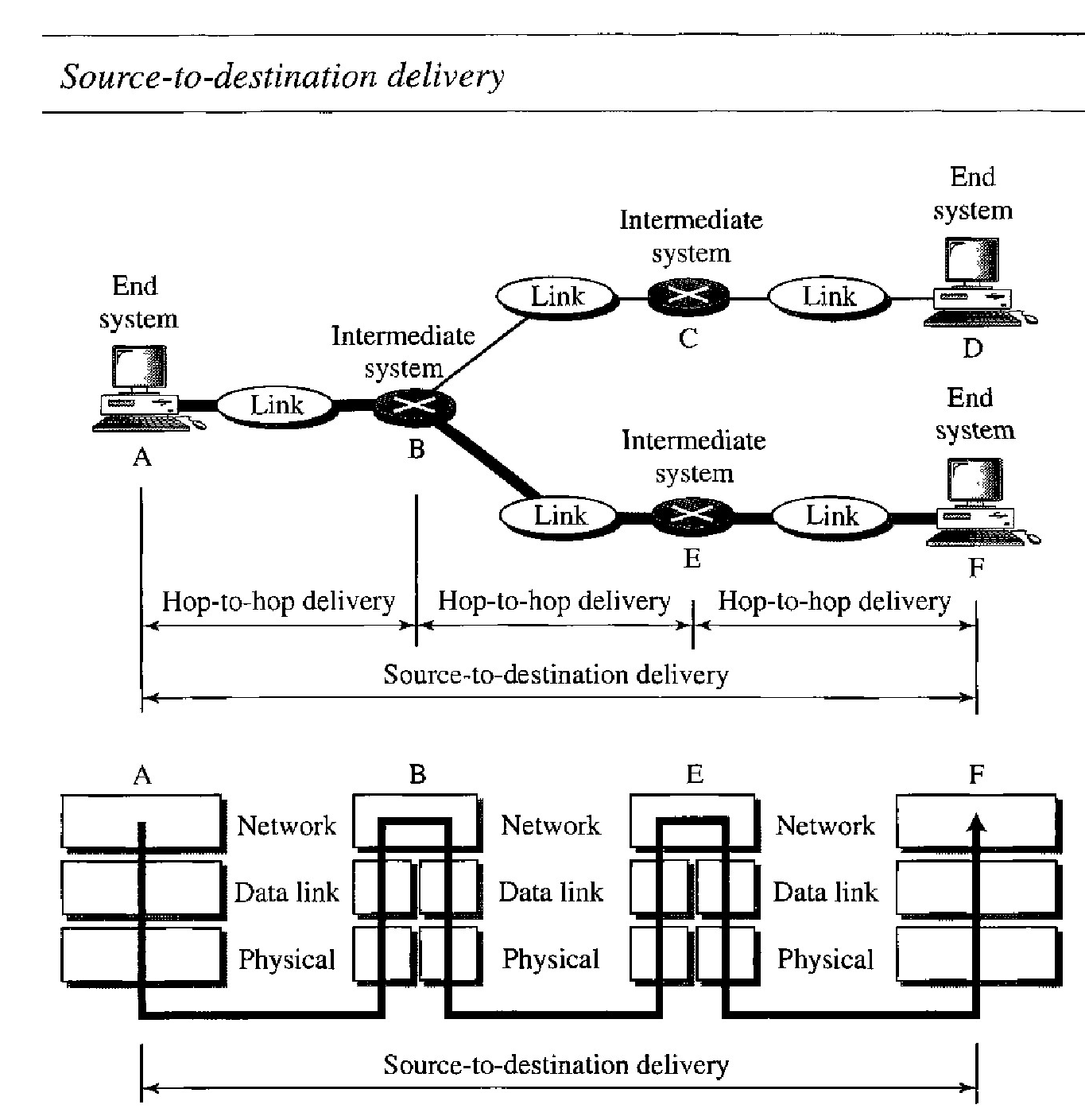
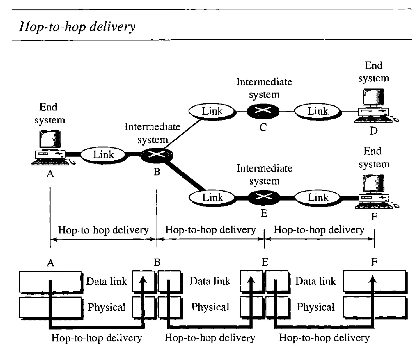
Q. illustrates hop-to-hop (node-to-node) delivery by the data link layer.
As the figure shows, communication at the data link layer occurs between two adjacent nodes. To send data from A to F, three partial deliveries are made.
First, the data link layer at A sends a frame to the data link layer at B (a router).
Second, the data link layer at B sends a new frame to the data link layer at E. Finally, the data link layer at E sends a new frame to the data link layer at F.
Note that the frames that are exchanged between the three nodes have different values in the headers. The frame from A to B has B as the destination address and A as the source address.
The frame from B to E has E as the destination address and B as the source address. The frame from E to F has F as the destination address and E as the source address. The values of the trailers can also be different if error checking includes the header of the frame.
Q. Illustrate Source-to-destination delivery and role of network layer
As the figure shows, now we need a source-to-destination delivery. The network layer at A sends the packet to the network layer at B.
When the packet arrives at router B, the router makes a decision based on the final destination (F) of the packet.
As we will see in later chapters, router B uses its routing table to find that the next hop is router E.
The network layer at B, therefore, sends the packet to the network layer at E. The network layer at E, in turn, sends the packet to the network layer at F.