TCP / IP Network Models
The TCP/IP protocol suite was developed prior to the OSI model. Therefore, the layers in the TCP/IP protocol suite do not exactly match those in the OSI model.
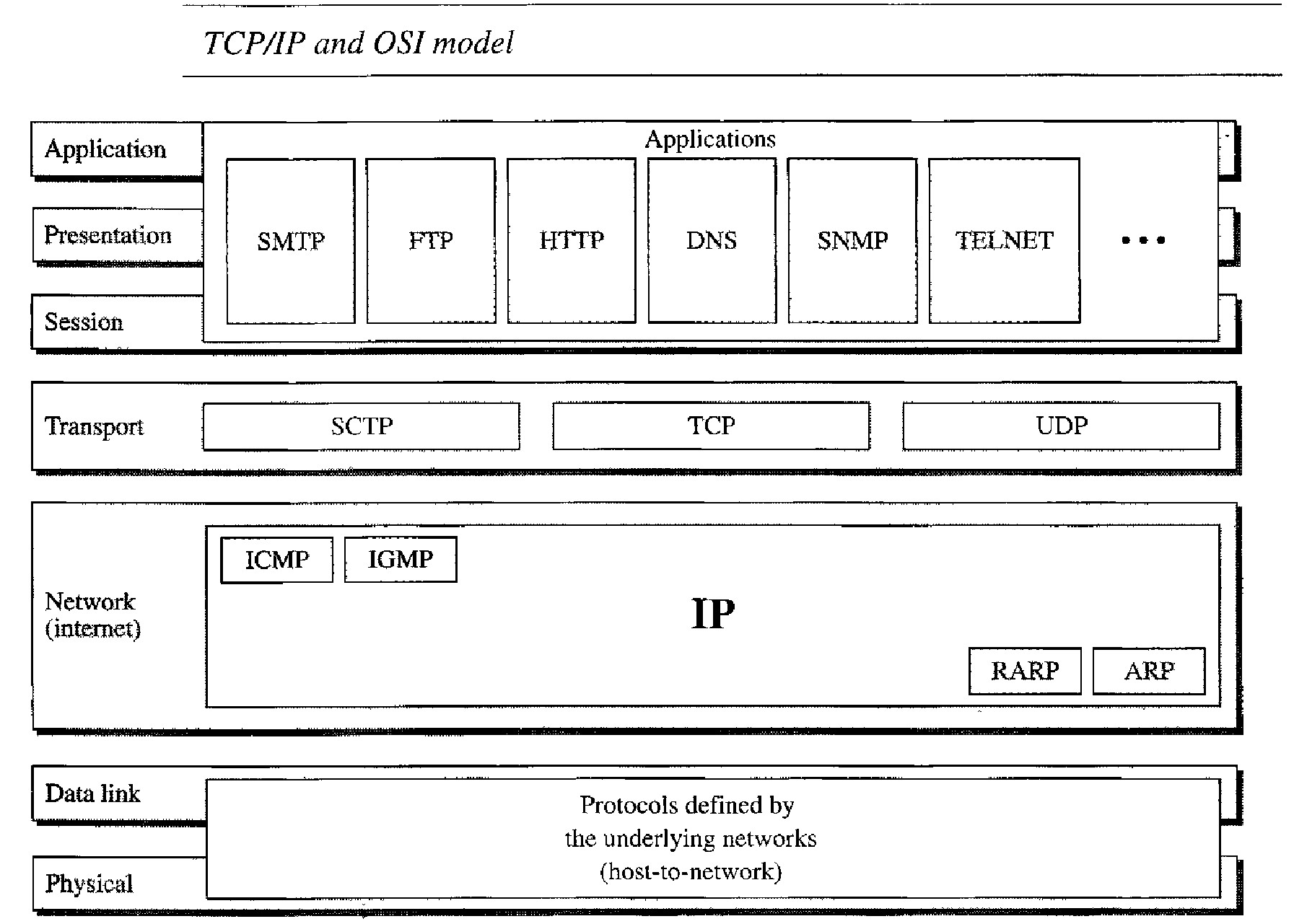
The original TCP/IP protocol suite was defined as having four layers: host-to-network, internet, transport, and application.
However, when TCP/IP is compared to OSI, we can say that the host-to-network layer is equivalent to the combination of the physical and data link layers.
The internet layer is equivalent to the network layer, and the application layer is roughly doing the job of the session, presentation, and application layers with the transport layer in TCPIIP taking care of part of the duties of the session layer.
TCP/IP is a hierarchical protocol made up of interactive modules, each of which provides a specific functionality; however, the modules are not necessarily interdependent. Whereas the OSI model specifies which functions belong to each of its layers, the layers of the TCP/IP protocol suite contain relatively independent protocols that can be mixed and matched depending on the needs of the system. The term hierarchical means that each upper-level protocol is supported by one or more lower-level protocols.
Layers of TCP / IP
Physical and Data Link Layers :
At the physical and data link layers, TCP/IP does not define any specific protocol. It supports all the standard and proprietary protocols.
A network in a TCP/IP internetwork can be a local-area network or a wide-area network.
Network Layer :
At the network layer (or, more accurately, the internetwork layer), TCP/IP supports the Internetworking Protocol. IP, in turn, uses four supporting protocols: ARP, RARP, ICMP, and IGMP.
Transport Layer :
Traditionally the transport layer was represented in TCP/IP by two protocols: TCP and UDP.
IP is a host-to-host protocol, meaning that it can deliver a packet from one physical device to another. UDP and TCP are transport level protocols responsible for delivery of a message from a process (running program) to another process.
Application Layer :
The application layer in TCP/IP is equivalent to the combined session, presentation, and application layers in the OSI model.
Inter-networking Protocol (IP)
The Internetworking Protocol (IP) is the transmission mechanism used by the TCP/IP protocols.
It is an unreliable and connectionless protocol-a best-effort delivery service. The term best effort means that IP provides no error checking or tracking.
IP transports data in packets called datagrams, each of which is transported sepa- rately. Datagrams can travel along different routes and can arrive out of sequence or be duplicated. IP does not keep track of the routes and has no facility for reordering datagrams once they arrive at their destination.
Address Resolution Protocol
The Address Resolution Protocol (ARP) is used to associate a logical address with a physical address.
On a typical physical network, such as a LAN, each device on a link is identified by a physical or station address, usually imprinted on the network interface card (NIC).
ARP is used to find the physical address of the node when its Internet address is known.
Reverse Address Resolution Protocol
The Reverse Address Resolution Protocol (RARP) allows a host to discover its Inter- net address when it knows only its physical address.
It is used when a computer is connected to a network for the first time or when a diskless computer is booted.
Internet Control Message Protocol
The Internet Control Message Protocol (ICMP) is a mechanism used by hosts and gateways to send notification of datagram problems back to the sender.
ICMP sends query and error reporting messages.
Internet Group Message Protocol
The Internet Group Message Protocol (IGMP) is used to facilitate the simultaneous transmission of a message to a group of recipients.
User Datagram Protocol
The User Datagram Protocol (UDP) is the simpler of the two standard TCP/IP transport protocols.
It is a process-to-process protocol that adds only port addresses, checksum error control, and length information to the data from the upper layer.
Transmission Control Protocol
The Transmission Control Protocol (TCP) provides full transport-layer services to applications.
TCP is a reliable stream transport protocol. The term stream, in this context, means connection-oriented: A connection must be established between both ends of a transmission before either can transmit data.
At the sending end of each transmission, TCP divides a stream of data into smaller units called segments.
Each segment includes a sequence number for reordering after receipt, together with an acknowledgment number for the segments received. Segments are carried across the internet inside of IP datagrams. At the receiving end, TCP collects each datagram as it comes in and reorders the transmission based on sequence numbers.
ADDRESSING
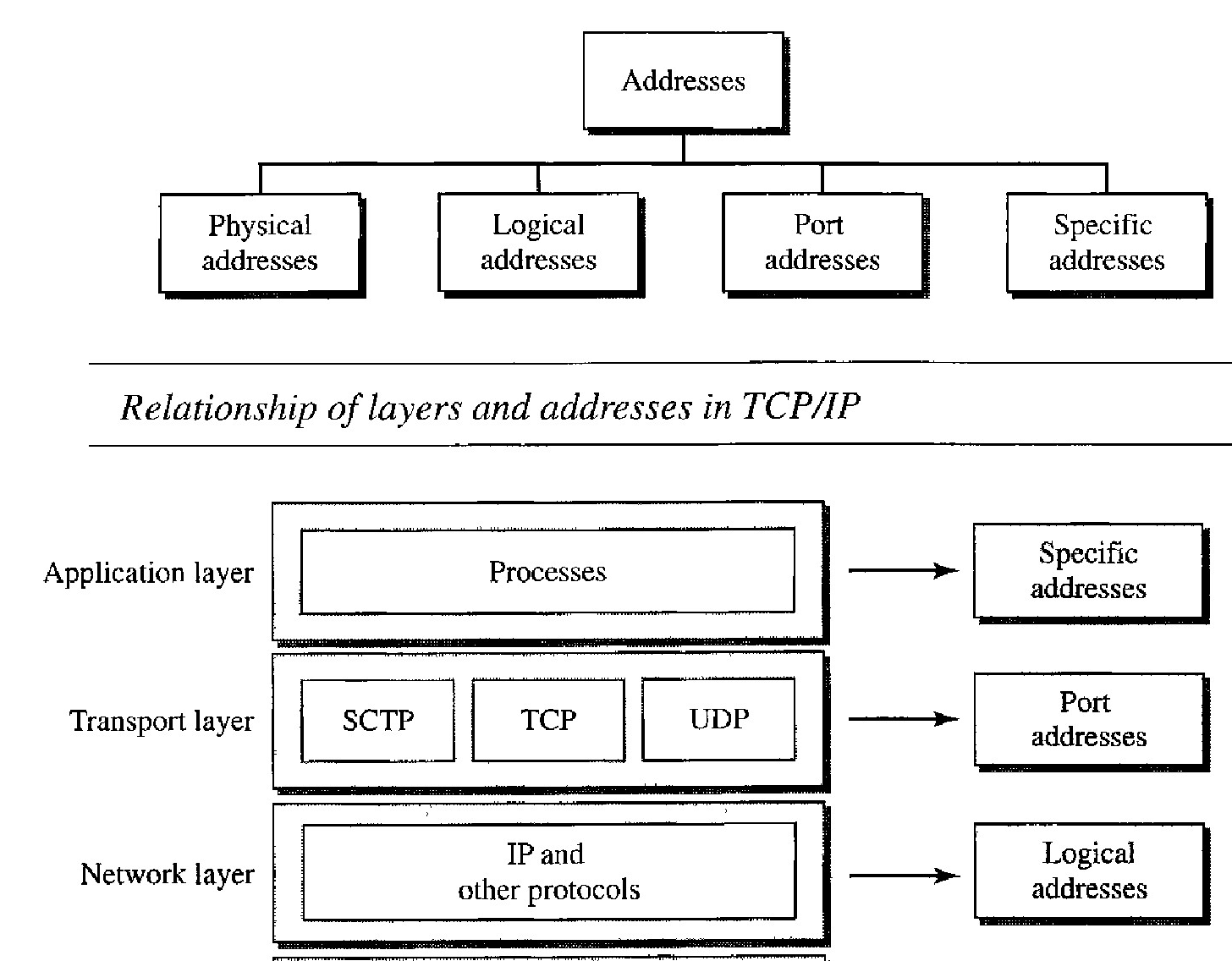
Four levels of addresses are used in an internet employing the TCP/IP protocols:
Physical Addresses :
The physical address, also known as the link address, is the address of a node as defined by its LAN or WAN.
It is included in the frame used by the data link layer. It is the lowest-level address.
The physical addresses have authority over the network (LAN or WAN). The size and format of these addresses vary depending on the network.
For example, Ethernet uses a 6-byte (48-bit) physical address that is imprinted on the network interface card (NIC). 07:01:02:01 :2C:4B -> A 6-byte (12 hexadecimal digits) physical address
Logical Addresses
Logical addresses are necessary for universal communications that are independent of underlying physical networks.
Physical addresses are not adequate in an internetwork environment where different networks can have different address formats. A universal addressing system is needed in which each host can be identified uniquely, regardless of the underlying physical network.
he logical addresses are designed for this purpose. A logical address in the Internet is currently a 32-bit address that can uniquely define a host connected to the Internet.
No two publicly addressed and visible hosts on the Internet can have the same IP address. The physical addresses will change from hop to hop, but the logical addresses usually remain the same.
Port Addresses
The IP address and the physical address are necessary for a quantity of data to travel from a source to the destination host.
However, arrival at the destination host is not the final objective of data communications on the Internet.
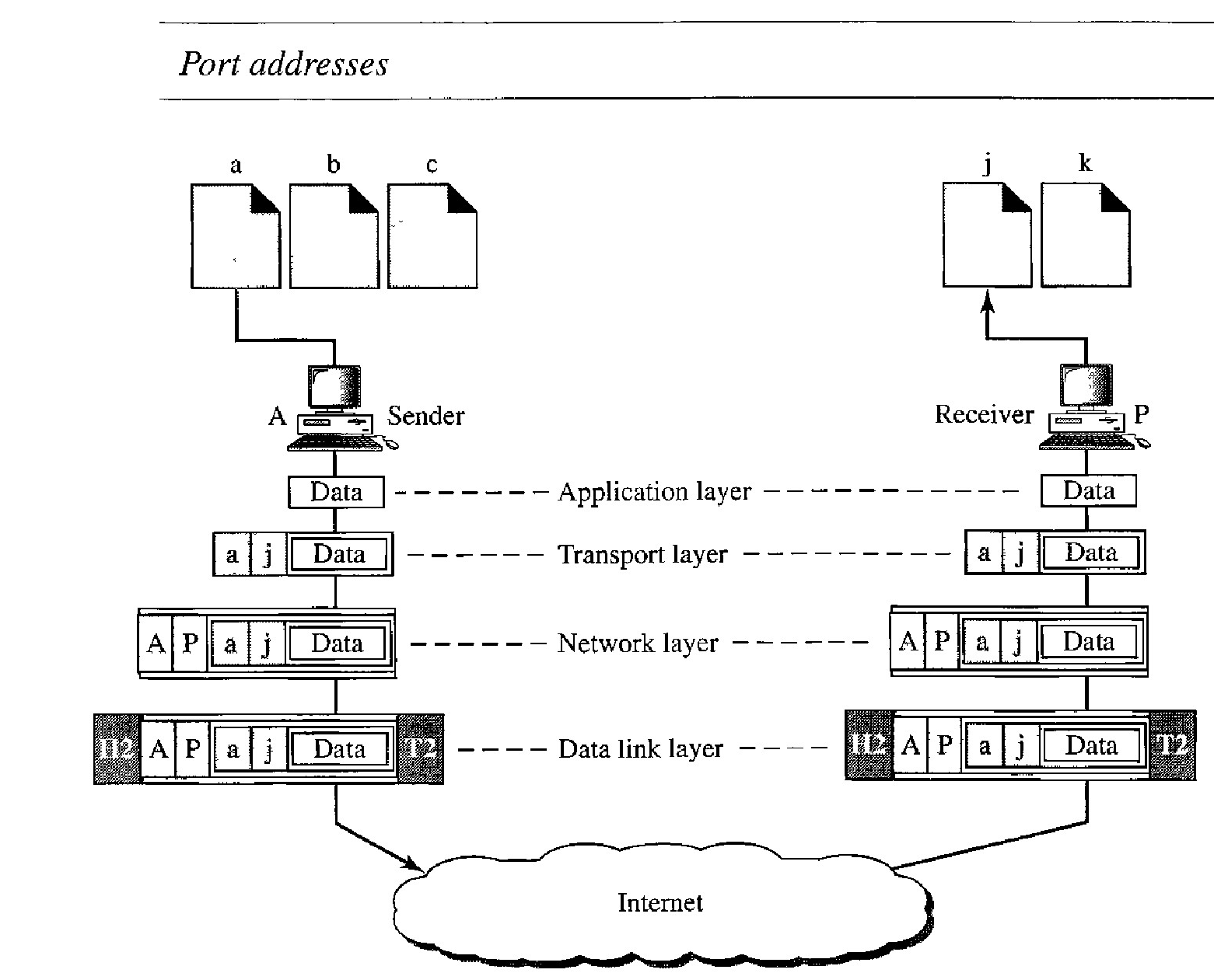
The end objective of Internet communication is a process communicating with another process. For example, computer A can communicate with computer C by using TELNET. At the same time, computer A com- municates with computer B by using the File Transfer Protocol (FTP).
For these processes to receive data simultaneously, we need a method to label the different processes. In other words, they need addresses. In the TCP/IP architecture, the label assigned to a process is called a port address. A port address in TCP/IP is 16 bits in length.The physical addresses change from hop to hop, but the logical and port addresses usually remain the same.
Specific Addresses
Some applications have user-friendly addresses that are designed for that specific address. Examples include the e-mail address (for example, [email protected]) and the Universal Resource Locator (URL) (for example, www.mhhe.com).
The first defines the recipient of an e-mail; the second is used to find a document on the World Wide Web . These addresses, however, get changed to the corresponding port and logical addresses by the sending computer.
Case Study : Importance of Physical addresses
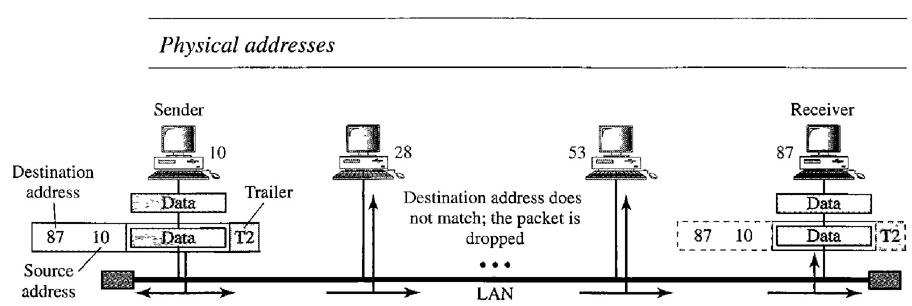
A node with physical address 10 sends a frame to a node with physical address 87. The two nodes are connected by a link (bus topology LAN).
At the data link layer, this frame contains physical (link) addresses in the header. These are the only addresses needed. The rest of the header contains other information needed at this level.
The trailer usually contains extra bits needed for error detection.
The computer with physical address lOis the sender, and the computer with physical address 87 is the receiver. The data link layer at the sender receives data from an upper layer. It encapsulates the data in a frame, adding a header and a trailer.
The header, among other pieces of information, carries the receiver and the sender phys- ical (link) addresses. Note that in most data link protocols, the destination address, 87 in this case, comes before the source address (10 in this case).
In a bus topology, the frame is propagated in both directions (left and right). The frame propagated to the left dies when it reaches the end of the cable if the cable end is terminated appropriately.
The frame propagated to the right is sent to every station on the network. Each station with a physical addresses other than 87 drops the frame because the destination address in the frame does not match its own physical address. The intended destination computer, however, finds a match between the destination address in the frame and its own physical address. The frame is checked, the header and trailer are dropped, and the data part is decapsulated and delivered to the upper layer.
Case Study : Importance of Logical addresses
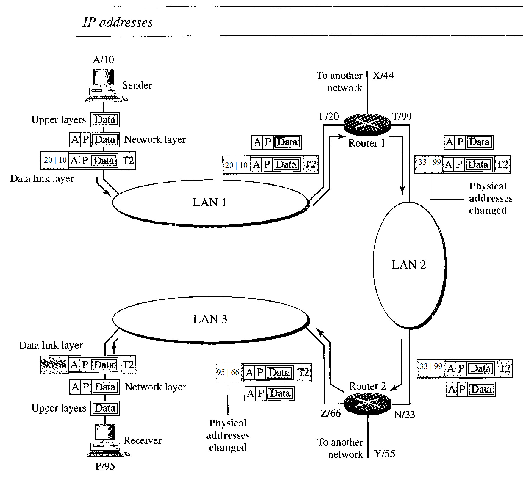
Figure below shows a part of an internet with two routers connecting three LANs.
Each device (computer or router) has a pair of addresses (logical and physical) for each connection. In this case, each computer is connected to only one link and therefore has only one pair of addresses.
Each router, however, is connected to three networks (only two are shown in the figure). So each router has three pairs of addresses, one for each connection.
The computer with logical address A and physical address 10 needs to send a packet to the computer with logical address P and physical address 95. We use letters to show the logical addresses and numbers for physical addresses.
he sender encapsulates its data in a packet at the network layer and adds two logical addresses (A and P). Note that in most protocols, the logical source address comes before the logical destination address (contrary to the order of physical addresses).
The network layer, however, needs to find the physical address of the next hop before the packet can be delivered.
The network layer consults its routing table and finds the logical address of the next hop (router I) to be F.
The ARP discussed previously finds the physical address of router 1 that corresponds to the logical address of 20. Now the network layer passes this address to the data link layer, which in tum, encapsulates the packet with physical destination address 20 and physical source address 10.
The frame is received by every device on LAN 1, but is discarded by all except router 1, which finds that the destination physical address in the frame matches with its own physical address.
The router decapsulates the packet from the frame to read the log- ical destination address P. Since the logical destination address does not match the router's logical address, the router knows that the packet needs to be forwarded.
The router consults its routing table and ARP to find the physical destination address of the next hop (router 2), creates a new frame, encapsulates the packet, and sends it to router 2.
Note the physical addresses in the frame. The source physical address changes from 10 to 99. The destination physical address changes from 20 (router 1 physical address) to 33 (router 2 physical address). The logical source and destination addresses must remain the same; otherwise the packet will be lost.
Case Study : Importance of Port addresses
The sending computer is running three processes at this time with port addresses a, b, and c. The receiving computer is running two processes at this time with port addresses j and k. Process a in the sending computer needs to communicate with process j in the receiving computer. Note that although both computers are using the same application, FTP, for example, the port addresses are different because one is a client program and the other is a server program.
To show that data from process a need to be delivered to process j, and not k, the transport layer encapsulates data from the application layer in a packet and adds two port addresses (a and j), source and destination.
The packet from the transport layer is then encapsulated in another packet at the network layer with logical source and destination addresses (A and P).
Finally, this packet is encapsulated in a frame with the physical source and destination addresses of the next hop.