Hamming Codes
These codes were originally designed with dmin = 3, which means that they can detect up to two errors or correct one single error.
The relationship between n and k in a Hamming code. We need to choose an integer m >= 3. The values of "n" and k are then calculated from mas n = 2m - 1 and k = n - m. The number of check bits r = m
A copy of a 4-bit dataword is fed into the generator that creates three parity checks \( R_1, R_2, R_0 \) as shown below:
\( R_0 = A_2 + A_1 + A_0 \) MODULO-2
\( R_1 = A_3 + A_2 + A_1 \) MODULO-2
\( R_2 = A_1 + A_0 + A_3 \) MODULO-2
The checker in the decoder creates a 3-bit syndrome (S2SlS0) in which each bit is the parity check for 4 out of the 7 bits in the received codeword:
\( S_0 = b_2 + b_1 + b_0 + q_0 \) MODULO-2
\( S_1 = b_3 + b_2 + b_1 + q_1 \) MODULO-2
\( S_2 = b_1 + b_0 + b_3 + q_2 \) MODULO-2
The equations used by the checker are the same as those used by the generator with the parity-check bits added to the right-hand side of the equation. The 3-bit syndrome creates eight different bit patterns (000 to 111) that can represent eight different conditions. These conditions define a lack of error or an error in 1 of the 7 bits of the received codeword.
The syndrome values in Table above are based on the syndrome bit calculations. For example, if q0 is in error, So is the only bit affected; the syndrome, therefore, is 001. If b2 is in error, S0 and S1 are the bits affected; the syndrome, therefore is 011. Similarly, if b1 is in error, all 3 syndrome bits are affected and the syndrome is 111.
| Syndrome | Error |
|---|---|
| 000 | none |
| 001 | q0 |
| 010 | q1 |
| 011 | b2 |
| 100 | q2 |
| 101 | b0 |
| 110 | b3 |
| 111 | b1 |
Path of three data-words from the sender to the destination
The dataword 0100 becomes the codeword 0100011. The codeword 0100011 is received. The syndrome is 000 (no error), the final dataword is 0100.
The dataword 0111 becomes the codeword 0111001. The codeword 0011001 is received. The syndrome is all. After flipping b2 (changing the 1 to 0), the final dataword is 0111.
The dataword 1101 becomes the codeword 1101000. The codeword 0001000 is received (two errors). The syndrome is 101, which means that b0 is in error. After flipping b0, we get 0000, the wrong dataword. This shows that our code cannot correct two errors.
CYCLIC CODES
Cyclic codes are special linear block codes with one extra property. In a cyclic code, if a codeword is cyclically shifted (rotated), the result is another codeword. For example, if 1011000 is a codeword and we cyclically left-shift, then 0110001 is also a codeword. In this case, if we call the bits in the first word a0 to a6, and the bits in the second word b0 to b6, we can shift the bits by using the following:
b1 = a0, b2 = a1, b3 = a2, b4 = a3, b5 = a4, b6 = a5, b0 = a6
In the rightmost equation, the last bit of the first word is wrapped around and becomes the first bit of the second word.
Cyclic Redundancy Check
We can create cyclic codes to correct errors. A category of cyclic codes called the cyclic redundancy check (CRC) is used in networks such as LANs and WANs.
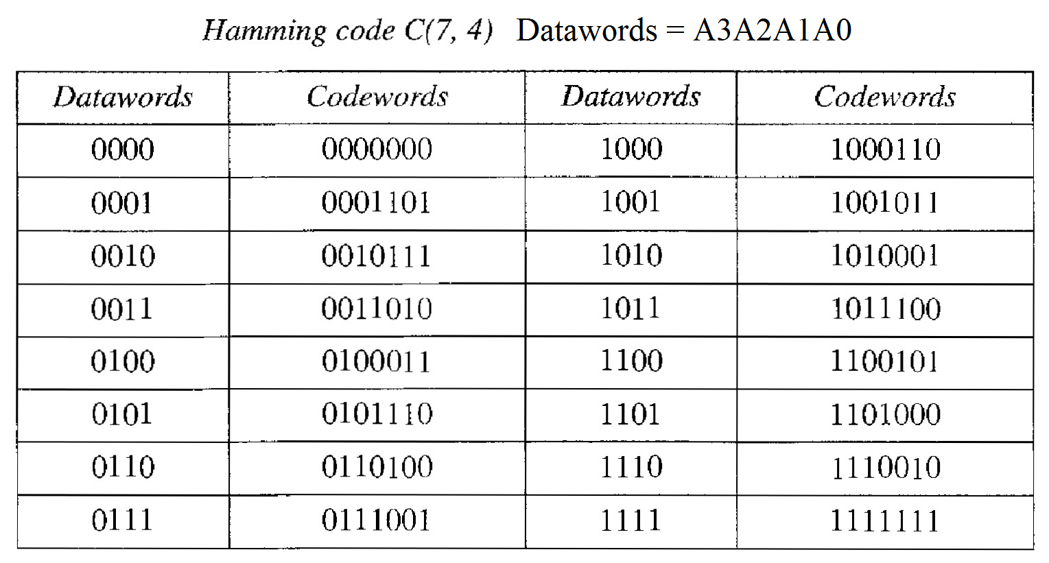
Table below shows an example of a CRC code. We can see both the linear and cyclic properties of this code.
Working of the Encoder :
In the encoder, the dataword has k bits (4 here); the codeword has n bits (7 here). The size of the dataword is augmented by adding n - k (3 here) 0' to the right-hand side of the word.
The n-bit result is fed into the generator. The generator uses a divisor of size n - k + 1 (4 here), predefined and agreed upon. The generator divides the augmented dataword by the divisor (modulo-2 division).
The quotient ofthe division is dis- carded; the remainder (R2R1R0) is appended to the dataword to create the codeword.
Working of the Decoder :
The decoder receives the possibly corrupted codeword. A copy of all n bits is fed to the checker which is a replica of the generator.
The remainder produced by the checker is a syndrome of n - k (3 here) bits, which is fed to the decision logic analyzer. The analyzer has a simple function.
If the syndrome bits are all Os, the 4 leftmost bits of the codeword are accepted as the dataword (interpreted as no error); otherwise, the 4 bits are discarded (error).
| Dataword | Codeword | Dataword | Codeword |
|---|---|---|---|
| 0000 | 0000000 | 1000 | 1000101 |
| 0001 | 0001011 | 1001 | 1001110 |
| 0010 | 0010110 | 1010 | 1010011 |
| 0011 | 0011101 | 1011 | 1011000 |
| 0100 | 0100111 | 1100 | 1100010 |
| 0101 | 0101100 | 1101 | 1101001 |
| 0110 | 0110001 | 1110 | 1110100 |
| 0111 | 0111010 | 1111 | 1111111 |
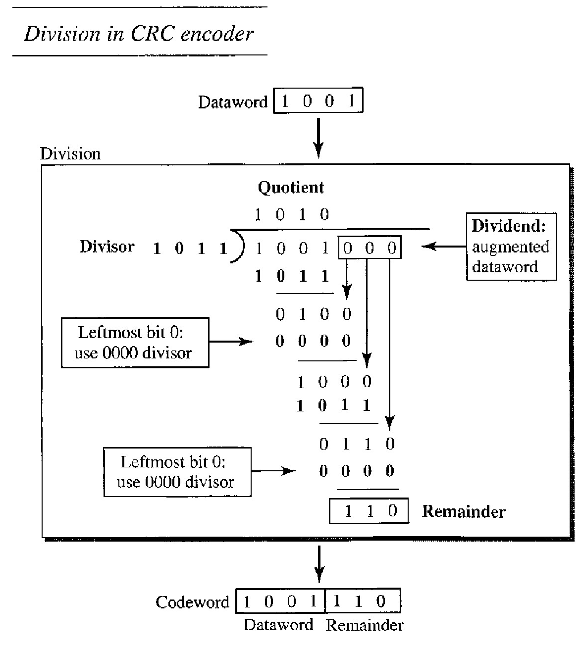
Encoder - Modulo 2 Division
The encoder takes the dataword and augments it with n - k number of 0's. It then divides the augmented dataword by the divisor,
The process of modulo-2 binary division is the same as the XOR operation.
As in decimal division, the process is done step by step. In each step, a copy of the divisor is XORed with the 4 bits of the dividend. The result of the XOR operation (remainder) is 3 bits (in this case), which is used for the next step after 1 extra bit is pulled down to make it 4 bits long.
There is one important point we need to remember in this type of division. If the leftmost bit of the dividend (or the part used in each step) is 0, the step cannot use the regular divisor; we need to use an all-0's divisor.
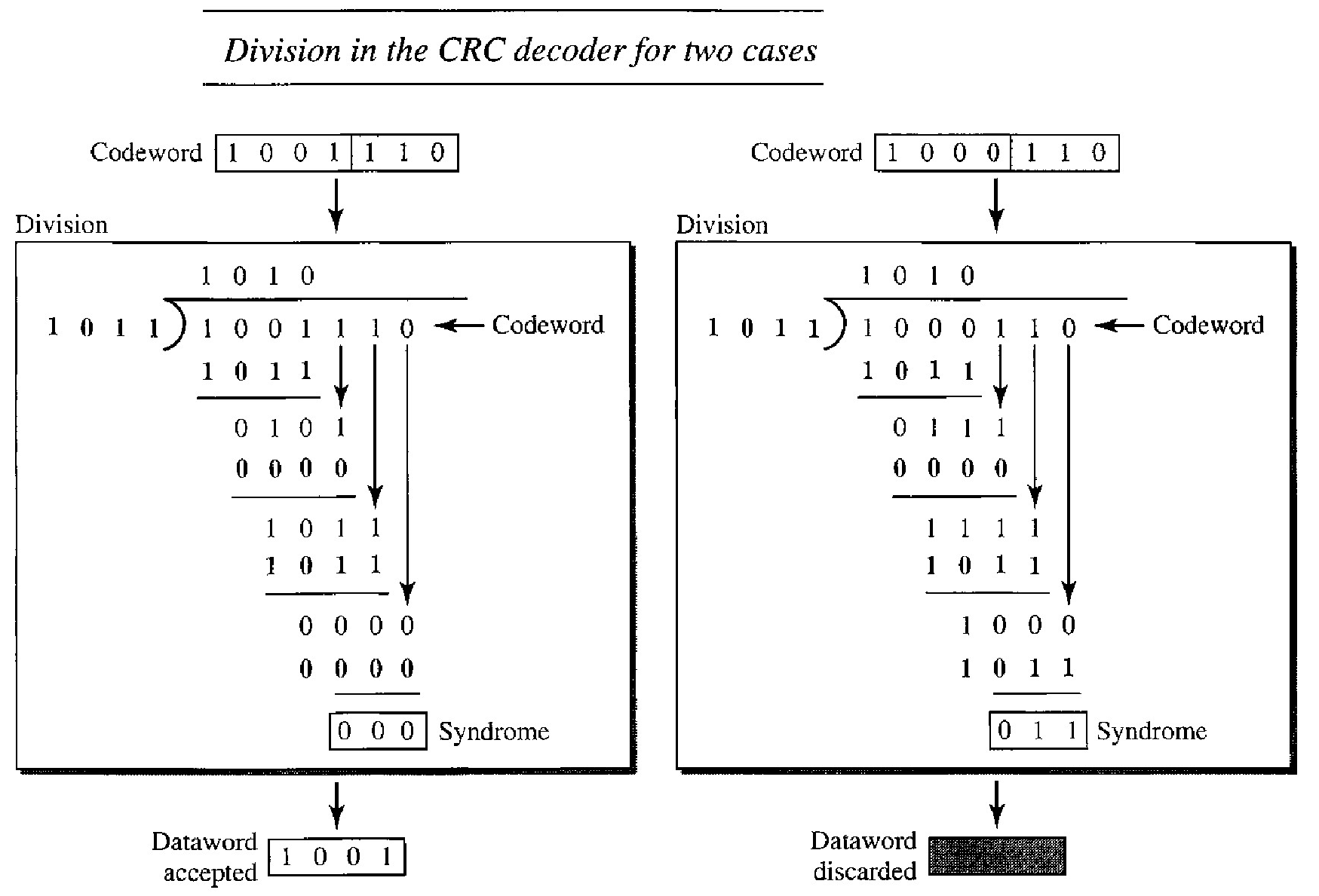
Decoder - Modulo 2 Division
The codeword can change during transmission. The decoder does the same division process as the encoder. The remainder of the division is the syndrome. If the syndrome is all as, there is no error; the dataword is separated from the received codeword and accepted. Otherwise, everything is discarded.
The lefthand figure shows the value of syndrome when no error has occurred; the syndrome is 000. The right-hand part of the figure shows the case in which there is one single error. The syndrome is not all as (it is 011).
CHECKSUM
The concept of the checksum is not difficult. Let us illustrate it with a few examples.
Example : Suppose our data is a list of five 4-bit numbers that we want to send to a destination. In addition to sending these numbers, we send the sum of the numbers. For example (7, 11, 12, 0, 6), we send (7, 11, 12,0,6,36), where 36 is the sum of the original numbers. The receiver adds the five numbers and compares the result with the sum. If the two are the same, the receiver assumes no error, accepts the five numbers, and discards the sum. Otherwise, there is an error somewhere and the data are not accepted.
Example : We can make the job of the receiver easier if we send the negative (complement) of the sum, called the checksum. In this case, we send (7, 11, 12,0,6, -36). The receiver can add all the num- bers received (including the checksum). If the result is 0, it assumes no error; otherwise, there is an error.
The previous example has one major drawback. All of our data can be written as a 4-bit word (they are less than 15) except for the checksum. One solution is to use one's complement arithmetic.
One's complement arithmetic
In this arithmetic, we can represent unsigned numbers between 0 and 2n - 1 using only n bits. If the number has more than "n" bits, the extra leftmost bits need to be added to the n rightmost bits (wrapping).
In one's complement arithmetic, a negative number can be represented by inverting all bits (changing 0 to 1 and 1 to 0). This is the same as subtracting the number from 2n - 1.
Q. How can we represent the number 21 in one's complement arithmetic using only four bits?
The number 21 in binary is 10101 (it needs five bits).
We can wrap the leftmost bit and add it to the four rightmost bits.
We have (0101 + 1) = 0110 or 6
Q. How can we represent the number -6 in one's complement arithmetic using only four bits?
In one's complement arithmetic, the negative or complement of a number is found by inverting all bits.
Positive 6 is 0110; negative 6 is 1001. If we consider only unsigned numbers, this is 9. In other words, the complement of 6 is 9.
Another way to find the complement of a number in one's complement arithmetic is to subtract the number from 2n - 1 (16 - 1 in this case).
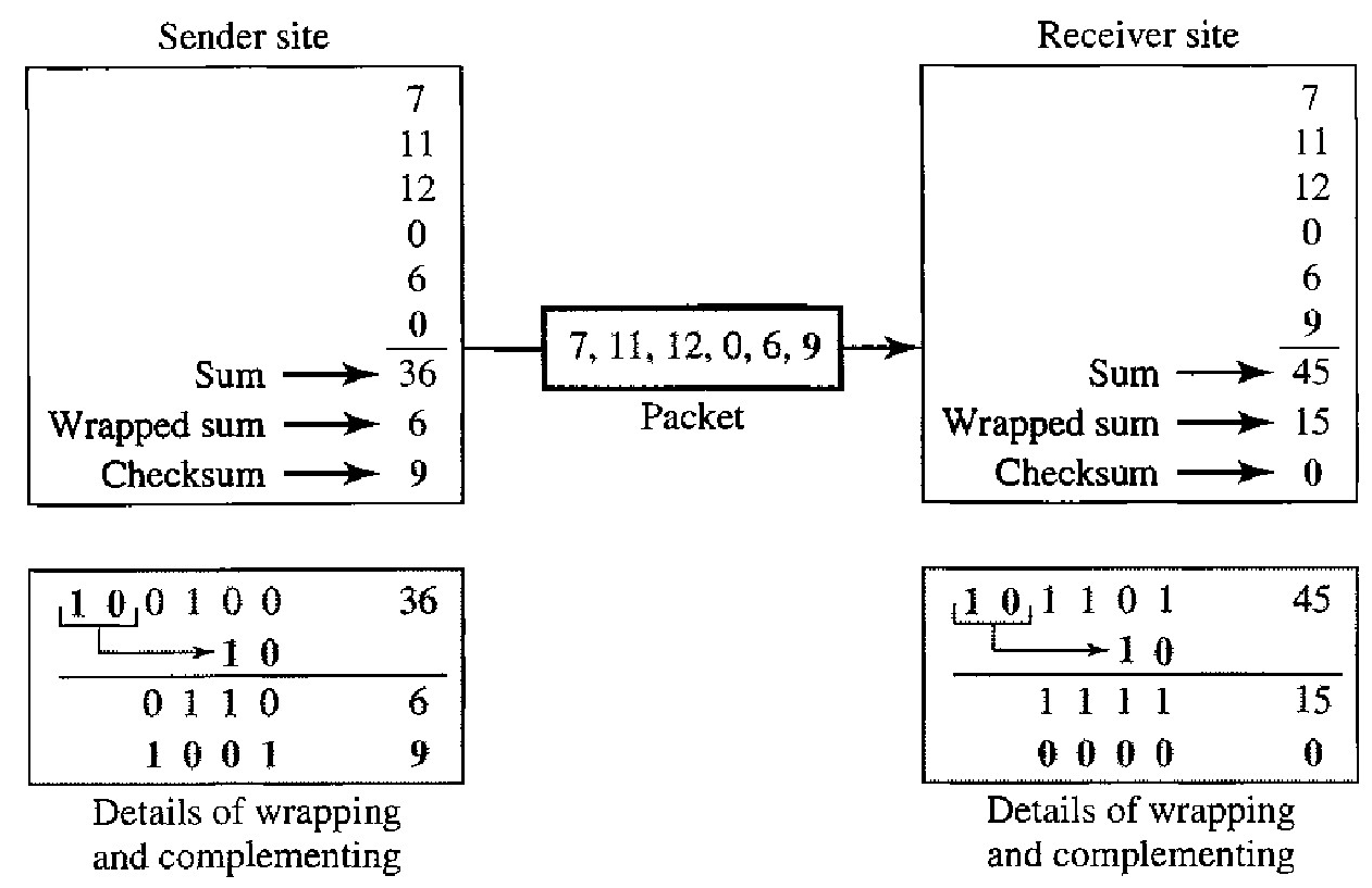
Operation of a CHECKSUM using One complement Arithmetic
Step 1 : The sender initializes the checksum to 0 and adds all data items and the checksum (the checksum is considered as one data item and is shown in color). The result is 36.
Step 2 : However, 36 cannot be expressed in 4 bits. The extra two bits are wrapped and added with the sum to create the wrapped sum value 6. In the figure, we have shown the details in binary. The sum is then complemented, resulting in the checksum value 9 (15 - 6 = 9).
Step 3 : The sender now sends six data items to the receiver including the checksum 9. The receiver follows the same procedure as the sender. It adds all data items (including the checksum); the result is 45.
Step 4 : The sum is wrapped and becomes 15. The wrapped sum is complemented and becomes O. Since the value of the checksum is 0, this means that the data is not corrupted. The receiver drops the checksum and keeps the other data items. If the checksum is not zero, the entire packet is dropped.