Network Layer: Internet Group Management Protocol (IGMP)
The IP protocol can be involved in two types of communication: unicasting and multicasting. Unicasting is the communication between one sender and one receiver. It is a one-to-one communication.
However, some processes sometimes need to send the same message to a large number of receivers simultaneously. This is called multicasting, which is a one-to-many communication.
Multicasting has many applications. For example, multiple stockbrokers can simultaneously be informed of changes in a stock price, or travel agents can be informed of a plane cancellation. Some other applications include distance learning and video-on-demand.
The Internet Group Management Protocol (IGMP) is one of the necessary, but not sufficient, protocols that is involved in multicasting. IGMP is a companion to the IP protocol.
Group Management - IGMP
For multicasting in the Internet we need routers that are able to route multicast packets. The routing tables of these routers must be updated by using one of the multicasting routing protocols.
IGMP is not a multicasting routing protocol; it is a protocol that manages group membership. In any network, there are one or more multicast routers that distribute multicast packets to hosts or other routers. The IGMP protocol gives the multicast routers information about the membership status of hosts (routers) connected to the network.
A multicast router may receive thousands of multicast packets every day for different groups. If a router has no knowledge about the membership status of the hosts, it must broadcast all these packets. This creates a lot of traffic and consumes bandwidth. A better solution is to keep a list of groups in the network for which there is at least one loyal member. IGMP helps the multicast router create and update this list.
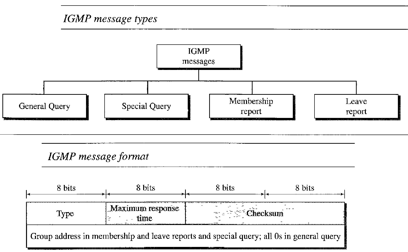
IGMP Messages : IGMPv2 has three types of messages: the query, the membership report, and the leave report. There are two types of query messages: general and special
Message Format :
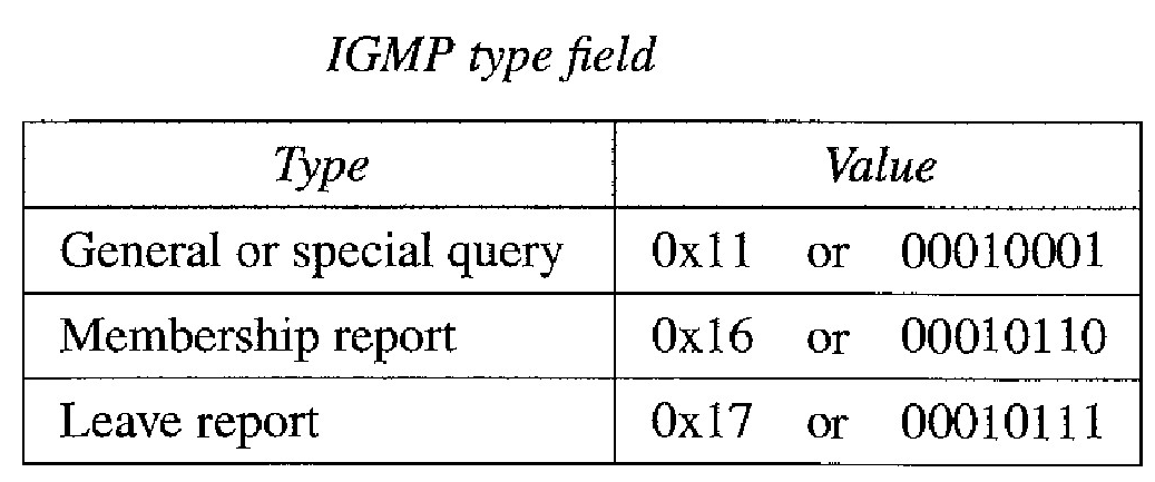
Type : This 8-bit field defines the type of message, as shown in Table below. The value of the type is shown in both hexadecimal and binary notation.
Maximum Response Time : This 8-bit field defines the amount of time in which a query must be answered. The value is in tenths of a second; for example, if the value is 100, it means 10 s. The value is nonzero in the query message; it is set to zero in the other two message types.
Checksum : This is a 16-bit field carrying the checksum. The checksum is calculated over the 8-byte message.
Group address : The value of this field is 0 for a general query message. The value defines the groupid (multicast address of the group) in the special query, the mem- bership report, and the leave report messages.
IGMP Operation
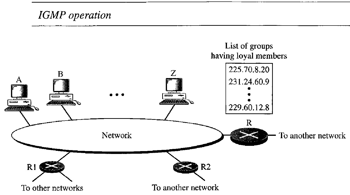
IGMP operates locally. A multicast router connected to a network has a list of multicast addresses of the groups with at least one loyal member in that network
For each group, there is one router that has the duty of distributing the multicast packets destined for that group. This means that if there are three multicast routers connected to a network, their lists of groupids are mutually exclusive. For example, in Figure above only router R distributes packets with the multicast address of 225.70.8.20.
A host or multicast router can have membership in a group. When a host has membership, it means that one of its processes (an application program) receives multicast packets from some group. When a router has membership, it means that a network connected to one of its other interfaces receives these multicast packets. We say that the host or the router has an interest in the group. In both cases, the host and the router keep a list of groupids and relay their interest to the distributing router.
Joining a Group : A host or a router can join a group. A host maintains a list of processes that have membership in a group. When a process wants to join a new group, it sends its request to the host. The host adds the name of the process and the name of the requested group to its list. If this is the first entry for this particular group, the host sends a membership report message. If this is not the first entry, there is no need to send the membership report since the host is already a member of the group; it already receives multicast packets for this group. The protocol requires that the membership report be sent twice, one after the other within a few moments. In this way, if the first one is lost or damaged, the second one replaces it.
Leaving a Group : When a host sees that no process is interested in a specific group, it sends a leave report. Similarly, when a router sees that none of the networks connected to its interfaces is interested in a specific group, it sends a leave report about that group. However, when a multicast router receives a leave report, it cannot immediately purge that group from its list because the report comes from just one host or router; there may be other hosts or routers that are still interested in that group. To make sure, the router sends a special query message and inserts the groupid, or multicast address, related to the group. The router allows a specified time for any host or router to respond. If, during this time, no interest (membership report) is received, the router assumes that there are no loyal members in the network and purges the group from its list.
Network Layer : Delivery, Forwarding, and Routing
Delivery refers to the way a packet is handled by the underlying networks under the control of the network layer. Forwarding refers to the way a packet is delivered to the next station. Routing refers to the way routing tables are created to help in forwarding.
The network layer supervises the handling of the packets by the underlying physical networks.We define this handling as the delivery of a packet.
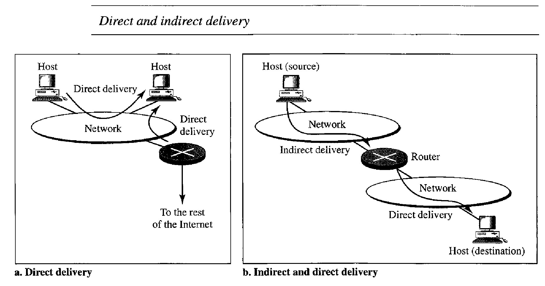
Direct Delivery : In a direct delivery, the final destination of the packet is a host connected to the same physical network as the deliverer. Direct delivery occurs when the source and destination of the packet are located on the same physical network or when the delivery is between the last router and the destination host. The sender can easily determine if the delivery is direct. It can extract the network address of the destination (using the mask) and compare this address with the addresses of the networks to which it is connected. If a match is found, the delivery is direct.
Indirect Delivery : If the destination host is not on the same network as the deliverer, the packet is deliv- ered indirectly. In an indirect delivery, the packet goes from router to router until it reaches the one connected to the same physical network as its final destination. Note that a delivery always involves one direct delivery but zero or more indirect deliveries. Note also that the last delivery is always a direct delivery.
FORWARDING :Forwarding means to place the packet in its route to its destination. Forwarding requires a host or a router to have a routing table. When a host has a packet to send or when a router has received a packet to be forwarded, it looks at this table to find the route to the final destination. However, this simple solution is impossible today in an internetwork such as the Internet because the number of entries needed in the routing table would make table lookups inefficient.
Forwarding Techniques
Several techniques can make the size of the routing table manageable and also handle issues such as security
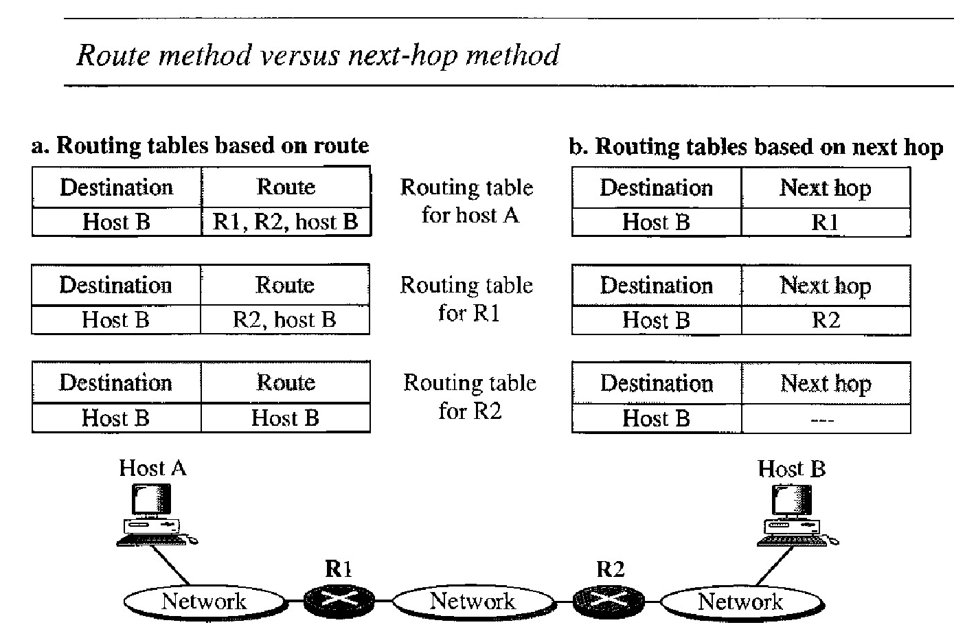
Next-Hop Method Versus Route Method : In this technique, the routing table holds only the address of the next hop instead of information about the complete route (route method). The entries of a routing table must be consistent with one another.
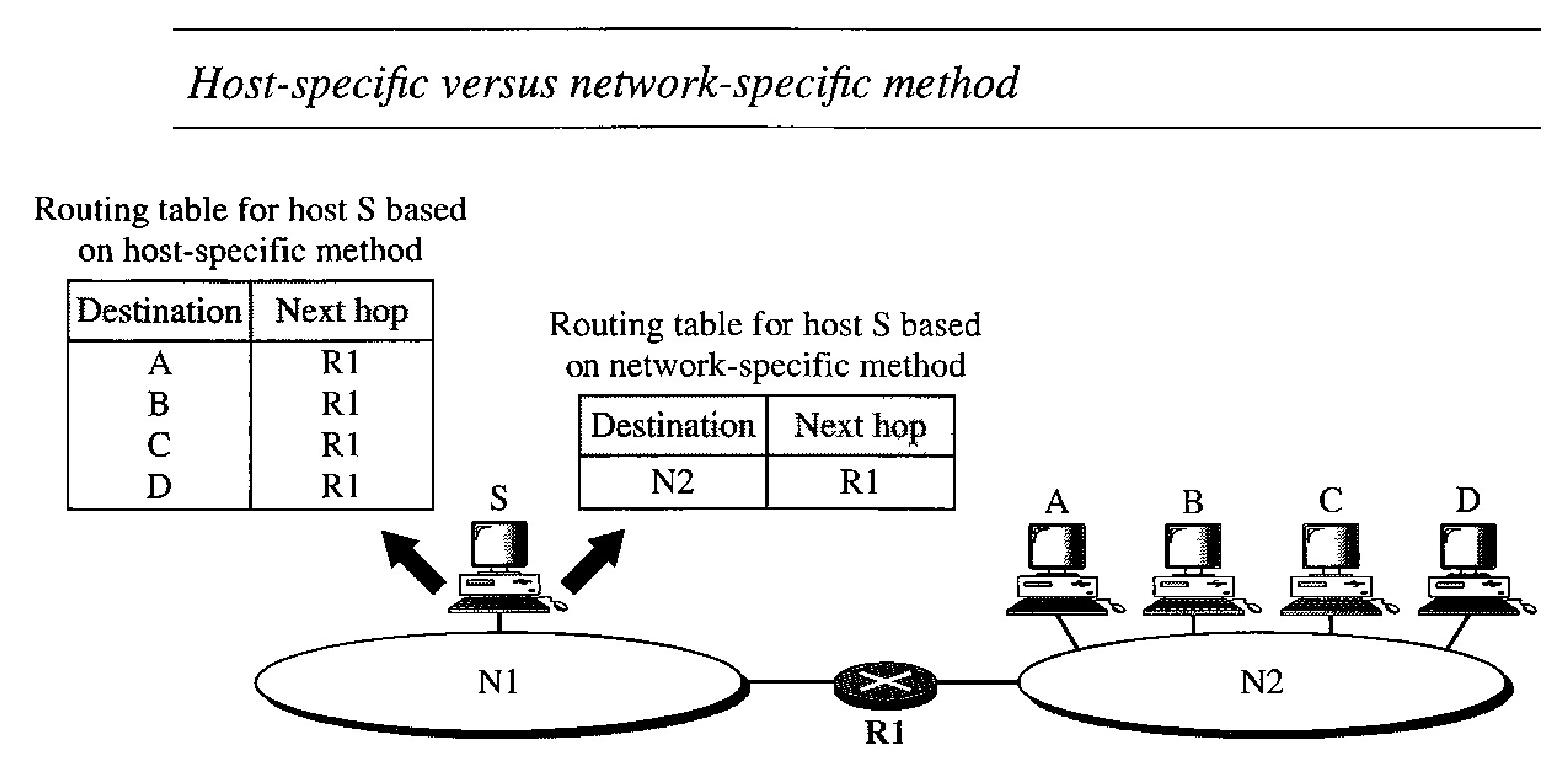
Network-Specific Method Versus Host-Specific Method : Here, instead of having an entry for every destination host connected to the same physical network (host-specific method), we have only one entry that defines the address of the destination network itself. In other words, we treat all hosts connected to the same network as one single entity. For example, if 1000 hosts are attached to the same network, only one entry exists in the routing table instead of 1000.
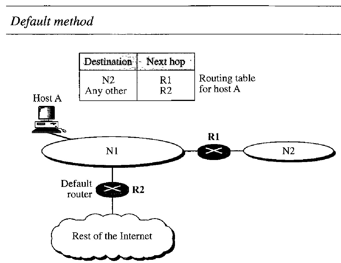
Default Method : Host A is connected to a network with two routers. Router R1 routes the packets to hosts connected to network N2. However, for the rest of the Internet, router R2 is used. So instead of listing all networks in the entire Internet, host A can just have one entry called the default (normally defined as network address 0.0.0.0).
Forwarding Process
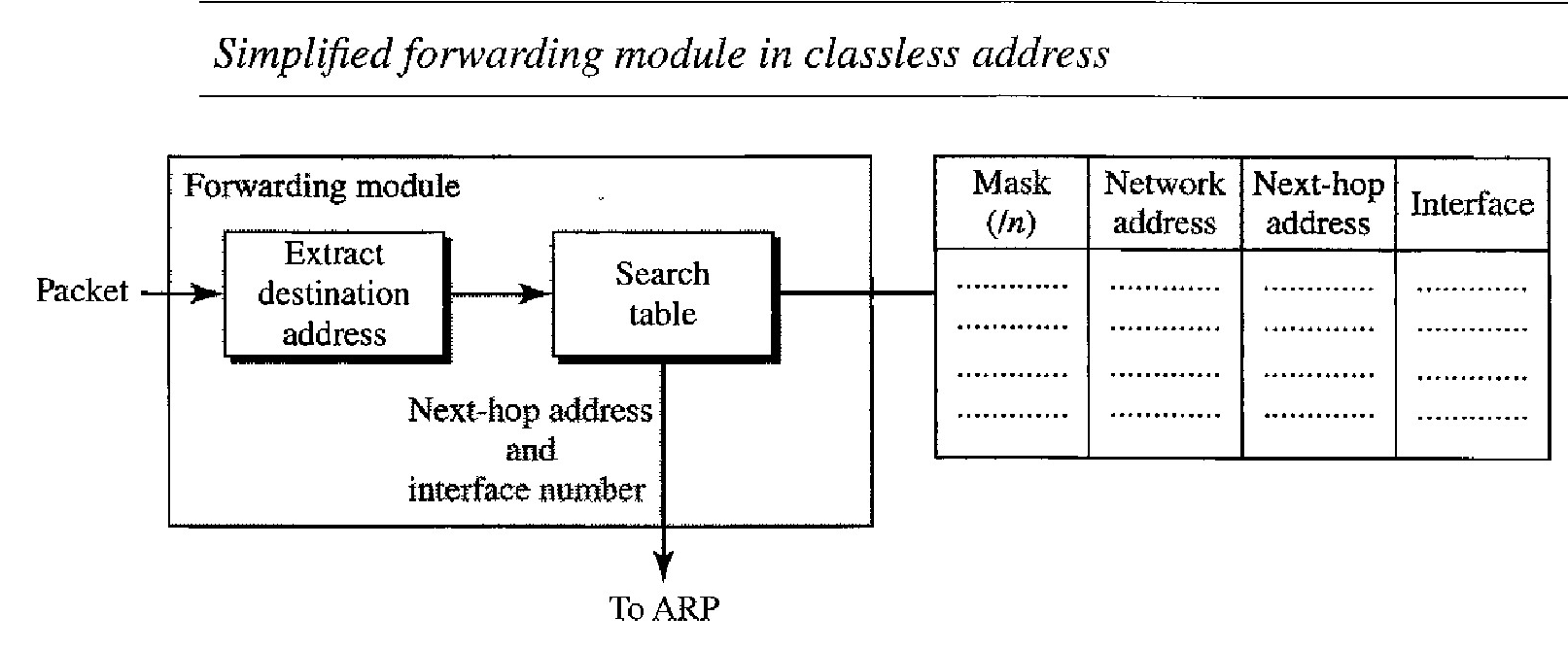
In classless addressing, the routing table needs to have one row of infonnation for each block involved. The table needs to be searched based on the network address (first address in the block).
Unfortunately, the destination address in the packet gives no clue about the network address. To solve the problem, we need to include the mask (/n) in the table; we need to have an extra column that includes the mask for the corresponding block.
In classless addressing, we need at least four celumns in a routing table.
We assume that hosts and routers use classless addressing because classful addressing can be treated as a special case of classless addressing.
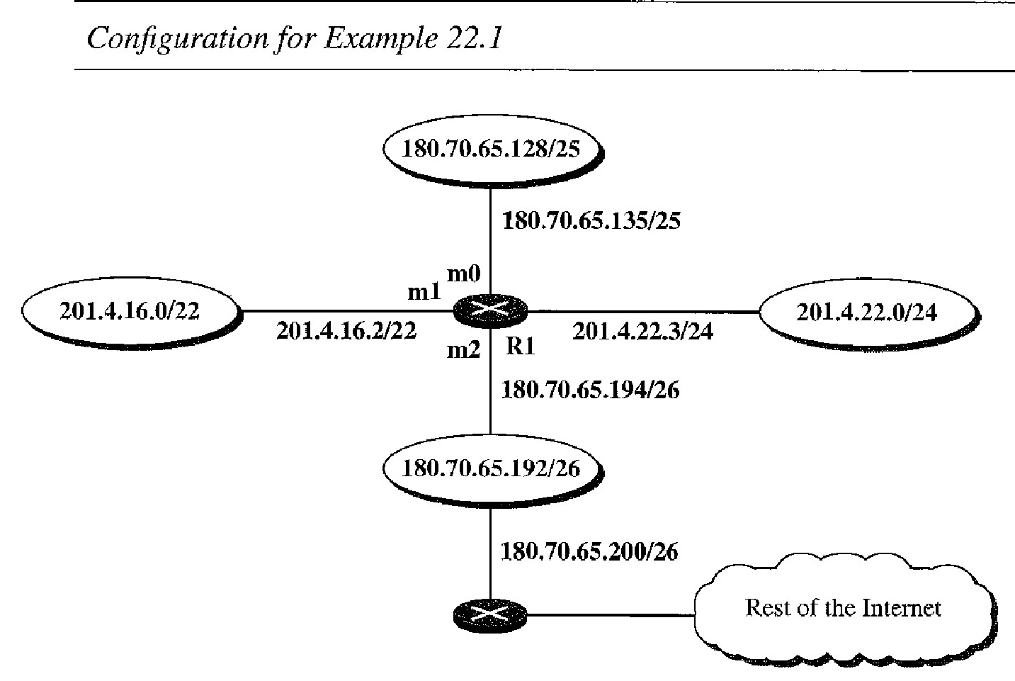
Make a routing table for router R1, using the configuration in Figure below
| Mask | Network Address | Next Hop | Interface |
|---|---|---|---|
| / 26 | 180.70.65.192 | - | m2 |
| / 25 | 180.70.65.128 | - | m0 |
| / 24 | 201.4.22.0 | - | m3 |
| / 22 | 201.4.16.0 | -- | m1 |
| Any | Any | 180.70.65.200 | m2 |
Q. Show the forwarding process if a packet arrives at Rl in Figure below with the destination address 180.70.65.140.
The router performs the following steps:
The first mask (/26) is applied to the destination address. The result is 180.70.65.128, which does not match the corresponding network address.
The second mask (/25) is applied to the destination address. The result is 180.70.65.128, which matches the corresponding network address. The next-hop address (the destination address of the packet in this case) and the interface number mO are passed to ARP for further processing.
Q. Show the forwarding process if a packet arrives at Rl in Figure above with the destination address 201.4.22.35.
The router performs the following steps:
The first mask (/26) is applied to the destination address. The result is 201.4.22.0, which does not match the corresponding network address (row 1)
The second mask (/25) is applied to the destination address. The result is 201.4.22.0, which does not match the corresponding network address (row 2).
The third mask (/24) is applied to the destination address. The result is 201.4.22.0, which matches the corresponding network address. The destination address of the packet and the interface number m3 are passed to ARP.
Q. Show the forwarding process if a packet arrives at R1 in Figure below with the destination address 18.24.32.78.
This time all masks are applied, one by one, to the destination address, but no matching network address is found.
When it reaches the end of the table, the module gives the next-hop address 180.70.65.200 and interface number m2 to ARP.
This is probably an outgoing package that needs to be sent, via the default router, to someplace else in the Internet.
Geographical Routing
To decrease the size of the routing table even further, we need to extend hierarchical routing to include geographical routing. We must divide the entire address space into a few large blocks.
We assign a block to North America, a block to Europe, a block to Asia, a block to Africa, and so on.
The routers of ISPs outside Europe will have only one entry for packets to Europe in their routing tables.
The routers of ISPs outside North America will have only one entry for packets to North America in their routing tables. And so on
Hierarchical Routing
To solve the problem of gigantic routing tables, we can create a sense of hierarchy in the routing tables.
The Internet today has a sense of hierarchy, it is divided into international and national ISPs. National ISPs are divided into regional ISPs, and regional ISPs are divided into local ISPs. If the routing table has a sense of hierarchy like the Internet architecture, the routing table can decrease in size.
Let us take the case of a local ISP. A local ISP can be assigned a single, but large block of addresses with a certain prefix length. The local ISP can divide this block into smaller blocks of different sizes and can assign these to individual users and organizations, both large and small.
If the block assigned to the local ISP starts with a.b.c.d/n, the ISP can create blocks starting with e.f.g.h/m, where m may vary for each customer and is greater than n.
All customers of the local ISP are defined as a.b.c.dln to the rest of the Internet. Every packet destined for one of the addresses in this large block is routed to the local ISP.
There is only one entry in every router in the world for all these cus- tomers. They all belong to the same group. Of course, inside the local ISP, the router must recognize the subblocks and route the packet to the destined customer.
Example of Hierarchical Routing
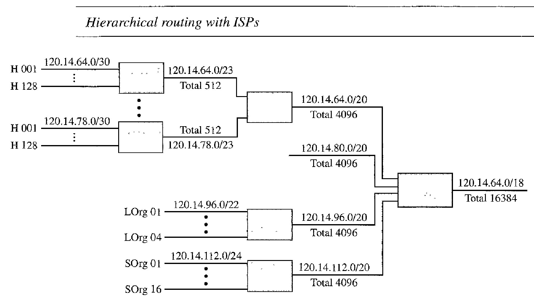
A regional ISP is granted 16,384 addresses starting from 120.14.64.0.
The regional ISP has decided to divide this block into four subblocks, each with 4096 addresses. Three of these subblocks are assigned to three local ISPs; the second subblock is reserved for future use. Note that the mask for each block is /20 because the original block with mask /18 is divided into 4 blocks.
The first local ISP has divided its assigned subblock into 8 smaller blocks and assigned each to a small ISP. Each small ISP provides services to 128 households (HOO1 to H128), each using four addresses.
Note that the mask for each small ISP is now /23 because the block is further divided into 8 blocks. Each household has a mask of /30, because a household has only four addresses (232-30 is 4).
The second local ISP has divided its block into 4 blocks and has assigned the addresses to four large organizations (LOrg01 to LOrg04). Note that each large organization has 1024 addresses, and the mask is /22.
The third local ISP has divided its block into 16 blocks and assigned each block to a small organization (SOrg01 to SOrg16). Each small organization has 256 addresses, and the mask is /24.
All routers in the Internet send a packet with destination address 120.14.64.0 to 120.14.127.255 to the regional ISP. The regional ISP sends every packet with destination address 120.14.64.0 to 120.14.79.255 to local ISPl. Local ISP1 sends every packet with destination address 120.14.64.0 to 120.14.64.3 to H001.
Address Aggregation
When we use classless addressing, it is likely that the number of routing table entries will increase. This is so because the intent of classless addressing is to divide up the whole address space into manageable blocks. The increased size of the table results in an increase in the amount of time needed to search the table. To alleviate the problem, the idea of address aggregation was designed.
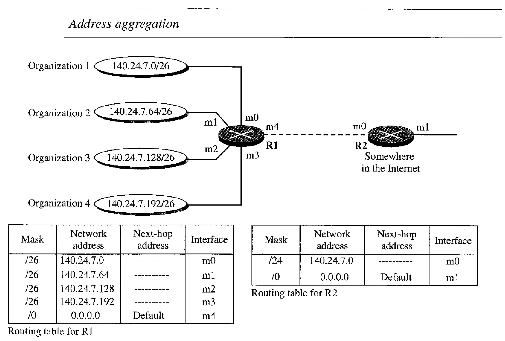
Router R1 is connected to networks of four organizations that each use 64 addresses. Router R2 is somewhere far from R1. Router R1 has a longer routing table because each packet must be correctly routed to the appropriate organization.
Router R2, on the other hand, can have a very small routing table. For R2, any packet with destination 140.24.7.0 to 140.24.7.255 is sent out from interface mO regardless of the organization number.
This is called address aggregation because the blocks of addresses for four organizations are aggregated into one larger block. Router R2 would have a longer routing table if each organization had addresses that could not be aggregated into one block.
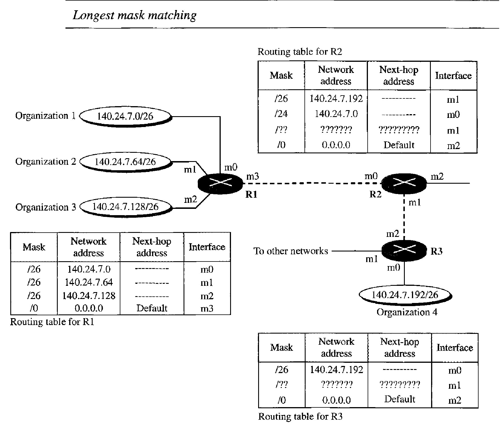
Longest Mask Matching
What happens if one of the organizations in Figure 22.7 is not geographically close to the other three? For example, if organization 4 cannot be connected to router Rl for some reason, can we still use the idea of address aggregation and still assign block 140.24.7.192/26 to organization 4 ?
The answer is yes because routing in classless addressing uses another principle, longest mask matching. This principle states that the routing table is sorted from the longest mask to the shortest mask. In other words, if there are three masks /27, /26, and /24, the mask /27 must be the first entry and /24 must be last. Let us see if this principle solves the situation in which organization 4 is separated from the other three organiza- tions.
Suppose a packet arrives for organization 4 with destination address 140.24.7.200. The first mask at router R2 is applied, which gives the network address 140.24.7.192. The packet is routed correctly from interface ml and reaches organization 4.
If, however, the routing table was not stored with the longest prefix first, applying the /24 mask would result in the incorrect routing of the packet to router Rl.