Number Systems
A number system of base, or radix, r is a system that uses distinct symbols for r digits. Numbers are represented by a string of digit symbols.
To determine the quantity that the number represents, it is necessary to multiply each digit by an integer power of r and then form the sum of all weighted digits.
For example, the decimal number system in everyday use employs the radix 10 system. The 10 symbols are 0, 1, 2, 3, 4, 5, 6, 7, 8, and 9. The string of digits 724.5 is interpreted to represent the quantity \( 7 * 10^2 + 2 * 10^1 + 4 * 10^0 + 5 * 10^{-1} \)
that is, 7 hundreds, plus 2 tens, plus 4 units, plus 5 tenths. Every decimal number can be similarly interpreted to find the quantity it represents. The binary number system uses the radix 2. The two digit symbols used are 0 and 1.
The string of digits 101101 is interpreted to represent the quantity \( 1 * 2^5 + 0 * 2^4 + 1 + 2^3 + 1 * 2^2 + 0 * 2^1 + 1 * 2^0 = 45 \)
To distinguish between different radix numbers, the digits will be enclosed in parentheses and the radix of the number inserted as a subscript.
For example, to show the equality between decimal and binary forty-five we will write (101101)2 = (45)10.
Besides the decimal and binary number systems, the octal (radix 8) and hexadecimal (radix 16) are important in digital computer work.
The eight symbols of the octal system are 0, 1, 2, 3, 4, 5, 6, and 7. The 16 symbols of the hexadecimal system are 0, 1, 2, 3, 4, 5, 6, 7, 8, 9, A, B, C, 0, E, and F.
The last six symbols are, unfortunately, identical to the letters of the alphabet and can cause confusion at times.
However, this is the convention that has been adopted. When used to represent hexadecimal digits, the symbols A, B, C, D, E, F correspond to the decimal numbers 10, 11, 12, 13, 14, 15, respectively.
A number in radix r can be converted to the familiar decimal system by forming the sum of the weighted digits. For example, octal 736.4 is converted to decimal as follows: \( (736.4)_8 = 7 * 8^2 + 3 * 8^1 + 6 * 8^0 + 4 * 8^{-1}\\ = 7 * 64 + 3 * 8 + 6 * 1 + 4/8 = (478.5)_{10} \)
The equivalent decimal number of hexadecimal F3 is obtained from the following calculation: \( (F3)_{16} = F * 16 + 3 = 15 * 16 + 3 = (243)_{10} \)
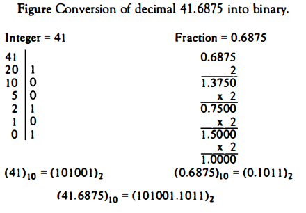
Conversion from decimal to its equivalent representation in the radix r system is carried out by separating the number into its integer and fraction parts and converting each part separately. The conversion of a decimal integer into a base r representation is done by successive divisions by r and accumulation of the remainders.
The conversion of a decimal fraction to radix r representation is accomplished by successive multiplications by r and accumulation of the integer digits so obtained. Figure below demonstrates these procedures.
The conversion of decimal 41.6875 into binary is done by first separating the number into its integer part 41 and fraction part .6875.
The integer part is converted by dividing 41 by r = 2 to give an integer quotient of 20 and a remainder of 1 The quotient is again divided by 2 to give a new quotient and remainder.
This process is repeated until the integer quotient becomes 0. The coefficients of the binary number are obtained from the remainders with the first remainder giving the low-order bit of the converted binary number.
The fraction part is converted by multiplying it by r = 2 to give an integer and a fraction. The new fraction (without the integer) is multiplied again by 2 to give a new integer and a new fraction.
This process is repeated until the fraction part becomes zero or until the number of digits obtained gives the required accuracy.
The coefficients of the binary fraction are obtained from the integer digits with the first integer computed being the digit to be placed next to the binary point.
Finally, the two parts are combined to give the total required conversion.
Octal and Hexadecimal Numbers
The conversion from and to binary, octal, and hexadecimal representation plays an important part in digital computers.
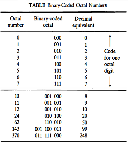
Since 23 = 8 and 24 = 16, each octal digit corresponds to three binary digits and each hexadecimal digit corresponds to four binary digits.
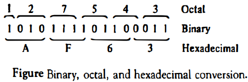
The conversion from binary to octal is easily accomplished by partitioning the binary number into groups of three bits each. The corresponding octal digit is then assigned to each group of bits and the string of digits so obtained gives the octal equivalent of the binary number.
Starting from the low-order bit, we partition the register into groups of three bits each (the sixteenth bit remains in a group by itself).
Each group of three bits is assigned its octal equivalent and placed on top of the register. The string of octal digits so obtained represents the octal equivalent of the binary number.
Conversion from binary to hexadecimal is similar except that the bits are divided into groups of four.
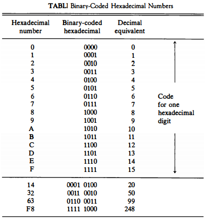
The registers in a digital computer contain many bits. Specifying the content of registers by their binary values will require a long string of binary digits.
It is more convenient to specify content of registers by their octal or hexadecimal equivalent.
The number of digits is reduced by one-third in the octal designation and by one-fourth in the hexadecimal designation. For example, the binary number 1111 1111 1111 has 12 digits.
It can be expressed in octals as 7777 (four digits) or in hexadecimal as FFF (three digits).
Computer manuals invariably choose either the octal or the hexadecimal designation for specifying contents of registers.
Decimal Representation
The binary number system is the most natural system for a computer, but people are accustomed to the decimal system.
One way to solve this conflict is to convert all input decimal numbers into binary numbers, let the computer perform all arithmetic operations in binary and then convert the binary results back to decimal for the human user to understand.
However, it is also possible for the computer to perform arithmetic operations directly with decimal numbers provided they are placed in registers in a coded form.
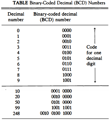
Decimal numbers enter the computer usually as binary-coded alphanumeric characters. These codes, introduced later, may contain from six to eight bits for each decimal digit. When decimal numbers are used for internal arithmetic computations, they are converted to a binary code with four bits per digit.
A binary code is a group of n bits that assume up to 2n distinct combinations of 1's and 0's with each combination representing one element of the set that is being coded.
A binary code will have some unassigned bit combinations if the number of elements in the set is not a multiple power of 2. The 10 decimal digits form such a set. A binary code that distinguishes among 10 elements must contain at least four bits, but six combinations will remain unassigned.
Numerous different codes can be obtained by arranging four bits in 10 distinct combinations. The bit assignment most commonly used for the decimal digits is the straight binary assignment listed in the first 10 entries of Table below.
This particular code is called binary-coded decimal and is commonly referred to by its abbreviation BCD.
It is very important to understand the difference between the conversion of decimal numbers into binary and the binary coding of decimal numbers.
For example, when converted to a binary number, the decimal number 99 is represented by the string of bits 1100011, but when represented in BCD, it becomes 1001 1001 .
The only difference between a decimal number represented by the familiar digit symbols 0, 1, 2, ... , 9 and the BCD symbols 0001, 0010, ... , 1001 is in the symbols used to represent the digits-the number itself is exactly the same.
Alphanumeric Representation
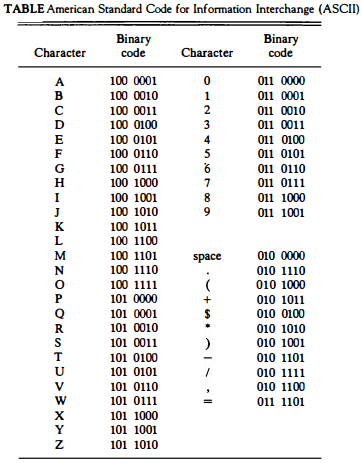
Many applications of digital computers require the handling of data that consist not only of numbers, but also of the letters of the alphabet and certain special characters.
An alphanumeric character set is a set of elements that includes the 10 decimal digits, the 26 letters of the alphabet and a number of special characters, such as $, + , and =.
Such a set contains between 32 and 64 elements (if only uppercase letters are included) or between 64 and 128 (if both uppercase and lowercase letters are included).
In the first case, the binary code will require six bits and in the second case, seven bits. The standard alphanumeric binary code is the ASCII (American Standard Code for Information Interchange), which uses seven bits to code 128 characters.
The binary code for the uppercase letters, the decimal digits, and a few special characters is listed in Table below.
Note that the decimal digits in ASCII can be converted to BCD by removing the three high-order bits, 011.
Binary codes play an important part in digital computer operations. The codes must be in binary because registers can only hold binary information. One must realize that binary codes merely change the symbols, not the meaning of the discrete elements they represent.
The operations specified for digital computers must take into consideration the meaning of the bits stored in registers so that operations are performed on operands of the same type.
Complements : 9s complement
Complements are used in digital computers for simplifying the subtraction operation and for logical manipulation. There are two types of complements for each base r system: the r's complement and the (r - 1)'s complement
When the value of the base r is substituted in the name, the two types are referred to as the 2's and 1's complement for binary numbers and the 10's and 9's complement for decimal numbers.
(r - 1)'s Complement
Given a number N in base r having n digits, the (r - 1)'s complement of N is defined as (rn - 1) - N. For decimal numbers r = 10 and r - 1 = 9, so the 9's complement of N is (10n - 1) - N.
Now, 10n represents a number that consists of a single 1 followed by n 0's.
10n - 1 is a number represented by n 9's. For example, with n = 4 we have 104 = 10000 and 104 - 1 = 9999.
It follows that the 9's complement of a decimal number is obtained by subtracting each digit from 9.
For example, the 9's complement of 546700 is 999999 - 546700 = 453299 and the 9's complement of 12389 is 99999 - 12389 = 87610.
Complements : 1's complement
For binary numbers, r = 2 and r - 1 = 1, so the 1's complement of N is (2n - 1) - N. Again, 2n is represented by a binary number that consists of a 1 followed by n 0's. 2n - 1 is a binary number represented by n 1's.
For example, with n = 4, we have 24 = (10000)2 and 24 - 1 = (1111)2. Thus the 1's complement of a binary number is obtained by subtracting each digit from 1.
However, the subtraction of a binary digit from 1 causes the bit to change from 0 to 1 or from 1 to 0. Therefore, the 1's complement of a binary number is formed by changing 1's into 0's and 0's into 1's.
For example, the 1's complement of 1011001 is 0100110 and the 1's complement of 0001111 is 1110000.
The (r - 1)'s complement of octal or hexadecimal numbers are obtained by subtracting each digit from 7 or F (decimal 15) respectively.
(r's) Complement : 10's complement
The r's complement of an n-digit number N in base r is defined as rn - N for N ≠ 0 and 0 for N = 0.
Comparing with the (r - 1)'s complement, we note that the r's complement is obtained by adding 1 to the (r - 1)'s complement since rn - N = [(rn - 1) - N] + 1.
Thus the 10's complement of the decimal 2389 is 7610 + 1 = 7611 and is obtained by adding 1 to the 9' s complement value.
The 2's complement of binary 101100 is 010011 + 1 = 010100 and is obtained by adding 1 to the 1's complement value.
Since 10n is a number represented by a 1 followed by n 0's, then 10n - N, which is the 10's complement of N, can be formed also be leaving all least significant 0's unchanged, subtracting the first nonzero least significant digit from 10, and then subtracting all higher significant digits from 9.
The 10's complement of 246700 is 753300 and is obtained by leaving the two zeros unchanged, subtracting 7 from 10, and subtracting the other three digits from 9.
(r's) Complement : 2's complement
The 2's complement can be formed by leaving all least significant 0's and the first 1 unchanged, and then replacing 1's by 0's and 0's by 1's in all other higher significant bits.
The 2's complement of 1101100 is 0010100 and is obtained by leaving the two low-order 0's and the first 1 unchanged, and then replacing 1's by 0's and 0's by 1's in the other four most significant bits.
In the definitions above it was assumed that the numbers do not have a radix point.
If the original number N contains a radix point, it should be removed temporarily to form the r's or (r - 1)'s complement.
The radix point is then restored to the complemented number in the same relative position.
It is also worth mentioning that the complement of the complement restores the number to its original value.
The r's complement of N is rn - N.
The complement of the complement is rn - (rn - N) = N giving back the original number.
Subtraction of Unsigned Numbers
The subtraction of two n-digit unsigned numbers M - N (N ≠ 0) in base r can be done as follows:
Add the minuend M to the r's complement of the subtrahend N. This performs M + (rn - N) = M - N + rn.
If M ≥ N, the sum will produce an end carry rn which is discarded, and what is left is the result M - N.
If M < N, the sum does not produce an end carry and is equal to rn - (N - M), which is the r's complement of (N - M). To obtain the answer in a familiar form, take the r' s complement of the sum and place a negative sign in front.
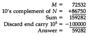
Consider, for example, the subtraction 72532 - 13250 = 59282. The 10's complement of 13250 is 86750. Therefore:
Now consider an example with M < N. The subtraction 13250 - 72532 produces negative 59282. Using the procedure with complements, we have
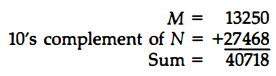
There is no end carry. Answer is negative 59282 = 10's complement of 40718
Since we are dealing with unsigned numbers, there is really no way to get an unsigned result for the second example.
When subtracting with complements, the negative answer is recognized by the absence of the end carry and the complemented result.
Subtraction with complements is done with binary numbers in a similar manner using the same procedure outlined above.
Using the two binary numbers X = 1010100 and Y = 1000011, we perform the subtraction X - Y and Y - X using 2's complements:
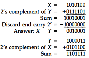
There is no end carry. Answer is negative 0010001 = 2's complement of 1101111
Fixed-Point Representation
Positive integers, including zero, can be represented as unsigned numbers. However, to represent negative integers, we need a notation for negative values.
In ordinary arithmetic, a negative number is indicated by a minus sign and a positive number by a plus sign. Because of hardware limitations, computers must represent everything with 1's and 0's, including the sign of a number.
As a consequence, it is customary to represent the sign with a bit placed in the leftmost position of the number. The convention is to make the sign bit equal to 0 for positive and to 1 for negative.
In addition to the sign, a number may have a binary (or decimal) point. The position of the binary point is needed to represent fractions, integers, or mixed integer-fraction numbers.
The representation of the binary point in a register is complicated by the fact that it is characterized by a position in the register.
There are two ways of specifying the position of the binary point in a register: by giving it a fixed position or by employing a floating-point representation.
The fixed-point method assumes that the binary point is always fixed in one position. The two positions most widely used are (1) a binary point in the extreme left of the register to make the stored number a fraction, and (2) a binary point in the extreme right of the register to make the stored number an integer.
In either case, the binary point is not actually present, but its presence is assumed from the fact that the number stored in the register is treated as a fraction or as an integer.
The floating-point representation uses a second register to store a number that designates the position of the decimal point in the first register.
Integer Representation
When an integer binary number is positive, the sign is represented by 0 and the magnitude by a positive binary number. When the number is negative, the sign is represented by 1 but the rest of the number may be represented in one of three possible ways:
1. Signed-magnitude representation
2. Signed-1's complement representation
3. Signed 2's complement representation
The signed-magnitude representation of a negative number consists of the magnitude and a negative sign. In the other two representations, the negative number is represented in either the 1's or 2's complement of its positive value.
As an example, consider the signed number 14 stored in an 8-bit register. + 14 is represented by a sign bit of 0 in the leftmost position followed by the binary equivalent of 14: 00001110.
Note that each of the eight bits of the register must have a value and therefore 0' s must be inserted in the most significant positions following the sign bit.
Although there is only one way to represent + 14, there are three different ways to represent - 14 with eight bits.
In signed-magnitude representation 1 0001110
In signed-1's complement representation 1 1110001
In signed-2's complement representation 1 1110010
The signed-magnitude representation of - 14 is obtained from + 14 by complementing only the sign bit.
The signed-1's complement representation of - 14 is obtained by complementing all the bits of + 14, including the sign bit. The signed-2' s complement representation is obtained by taking the 2' s complement of the positive number, including its sign bit.
The signed-magnitude system is used in ordinary arithmetic but is awkward when employed in computer arithmetic.
Therefore, the signed-complement is normally used. The 1' s complement imposes difficulties because it has two representations of 0 (+0 and - 0).
It is seldom used for arithmetic operations except in some older computers.
The 1's complement is useful as a logical operation since the change of 1 to 0 or 0 to 1 is equivalent to a logical complement operation.
Arithmetic Addition
The addition of two numbers in the signed-magnitude system follows the rules of ordinary arithmetic.
If the signs are the same, we add the two magnitudes and give the sum the common sign.
If the signs are different, we subtract the smaller magnitude from the larger and give the result the sign of the larger magnitude.
For example, (+25) + (-37) = - (37 - 25) = - 12 and is done by subtracting the smaller magnitude 25 from the larger magnitude 37 and using the sign of 37 for the sign of the result.
This is a process that requires the comparison of the signs and the magnitudes and then performing either addition or subtraction.
By contrast, the rule for adding numbers in the signed-2's complement system does not require a comparison or subtraction, only addition and complementation.
The procedure can be stated as follows: Add the two numbers, including their sign bits, and discard any carry out of the sign (leftmost) bit position.
Numerical examples for addition are shown below. Note that negative numbers must initially be in 2' s complement and that if the sum obtained after the addition is negative, it is in 2's complement form.
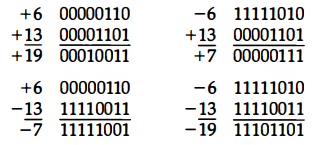
In each of the four cases, the operation performed is always addition, including the sign bits. Any carry out of the sign bit position is discarded, and negative results are automatically in 2' s complement form.
The complement form of representing negative numbers is unfamiliar to people used to the signed-magnitude system.
To determine the value of a negative number when in signed-2's complement, it is necessary to convert it to a positive number to place it in a more familiar form.
For example, the signed binary number 1111 1001 is negative because the leftmost bit is 1.
Its 2' s complement is 00000111, which is the binary equivalent of +7. We therefore recognize the original negative number to be equal to -7.
Arithmetic Subtraction
Subtraction of two signed binary numbers when negative numbers are in 2' s complement form can be stated as follows:
Take the 2's complement of the subtrahend (including the sign bit) and add it to the minuend (including the sign bit). A carry out of the sign bit position is discarded.
This procedure stems from the fact that a subtraction operation can be changed to an addition operation if the sign of the subtrahend is changed. This is demonstrated by the following relationship:
(±A) - (+B) = (±A) + (-B)
(±A) - (-B) = (±A) + (+B)
But changing a positive number to a negative number is easily done by taking its 2's complement.
The reverse is also true because the complement of a negative number in complement form produces the equivalent positive number.
Consider the subtraction of (-6) - (- 13) = +7. In binary with eight bits this is written as 11111010 - 11110011.
The subtraction is changed to addition by taking the 2's complement of the subtrahend (- 13) to give (+ 13). In binary this is 11111010 + 00001101 = 100000111. Removing the end carry, we obtain the correct answer 00000111 ( + 7).
It is worth noting that binary numbers in the signed-2's complement system are added and subtracted by the same basic addition and subtraction rules as unsigned numbers.
Therefore, computers need only one common hardware circuit to handle both types of arithmetic.
The user or programmer must interpret the results of such addition or subtraction differently depending on whether it is assumed that the numbers are signed or unsigned.
Overflow
When two numbers of n digits each are added and the sum occupies n + 1 digits, we say that an overflow occurred.
An overflow is a problem in digital computers because the width of registers is finite. A result that contains n + 1 bits cannot be accommodated in a register with a standard length of n bits. For this reason, many computers detect the occurrence of an overflow, and when it occurs, a corresponding flip-flop is set which can then be checked by the user.
The detection of an overflow after the addition of two binary numbers depends on whether the numbers are considered to be signed or unsigned. When two unsigned numbers are added, an overflow is detected from the end carry out of the most significant position.
In the case of signed numbers, the leftmost bit always represents the sign, and negative numbers are in 2' s complement form.
When two signed numbers are added, the sign bit is treated as part of the number and the end carry does not indicate an overflow.
An overflow cannot occur after an addition if one number is positive and the other is negative, since adding a positive number to a negative number produces a result that is smaller than the larger of the two original numbers.
An overflow may occur if the two numbers added are both positive or both negative. To see how this can happen, consider the following example. Two signed binary numbers, + 70 and + 80, are stored in two 8-bit registers.
The range of numbers that each register can accommodate is from binary + 127 to binary - 128. Since the sum of the two numbers is + I50, it exceeds the capacity of the 8-bit register.
This is true if the numbers are both positive or both negative. The two additions in binary are shown below together with the last two carries.
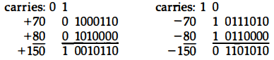
Note that the 8-bit result that should have been positive has a negative sign bit and the 8-bit result that should have been negative has a positive sign bit. If, however, the carry out of the sign bit position is taken as the sign bit of the result, the 9-bit answer so obtained will be correct.
Since the answer cannot be accommodated within 8 bits, we say that an overflow occurred. An overflow condition can be detected by observing the carry into the sign bit position and the carry out of the sign bit position. If these two carries are not equal, an overflow condition is produced.
This is indicated in the examples where the two carries are explicitly shown. If the two carries are applied to an exclusive-OR gate, an overflow will be detected when the output of the gate is equal to 1.
Decimal Fixed-Point Representation
The representation of decimal numbers in registers is a function of the binary code used to represent a decimal digit.
A 4-bit decimal code requires four flip-flops for each decimal digit. The representation of 4385 in BCD requires 16 flip-flops, four flip-flops for each digit. The number will be represented in a register with 16 flip-flops as follows: 0100 0011 1000 0101
By representing numbers in decimal we are wasting a considerable amount of storage space since the number of bits needed to store a decimal number in a binary code is greater than the number of bits needed for its equivalent binary representation.
Also, the circuits required to perform decimal arithmetic are more complex. However, there are some advantages in the use of decimal representation because computer input and output data are generated by people who use the decimal system.
Some applications, such as business data processing, require small amounts of arithmetic computations compared to the amount required for input and output of decimal data. For this reason, some computers and all electronic calculators perform arithmetic operations directly with the decimal data (in a binary code) and thus eliminate the need for conversion to binary and back to decimal.
Some computer systems have hardware for arithmetic calculations with both binary and decimal data. The representation of signed decimal numbers in BCD is similar to the representation of signed numbers in binary.
We can either use the familiar signed-magnitude system or the signed-complement system. The sign of a decimal number is usually represented with four bits to conform with the 4-bit code of the decimal digits.
It is customary to designate a plus with four 0' s and a minus with the BCD equivalent of 9, which is 1001 .
The signed-magnitude system is difficult to use with computers. The signed-complement system can be either the 9's or the 10's complement, but the 10's complement is the one most often used.
To obtain the 10' s complement of a BCD number, we first take the 9's complement and then add one to the least significant digit. The 9' s complement is calculated from the subtraction of each digit from 9.
The procedures developed for the signed-2's complement system apply also to the signed-10's complement system for decimal numbers. Addition is done by adding all digits, including the sign digit, and discarding the end carry.
Obviously, this assumes that all negative numbers are in 10's complement form. Consider the addition (+375) + (-240) = + 135 done in the signed 10's complement system.
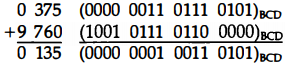
The 9 in the leftmost position of the second number indicates that the number is negative. 9760 is the 10's complement of 0240. The two numbers are added and the end carry is discarded to obtain + 135. Of course, the decimal numbers inside the computer must be in BCD, including the sign digits. The addition is done with BCD adders
The subtraction of decimal numbers either unsigned or in the signed-10' s complement system is the same as in the binary case. Take the 10' s complement of the subtrahend and add it to the minuend.
Floating-Point Representation
The floating-point representation of a number has two parts. The first part represents a signed, fixed-point number called the mantissa.
The second part designates the position of the decimal (or binary) point and is called the exponent. The fixed-point mantissa may be a fraction or an integer.
For example, the decimal number + 6132.789 is represented in floating-point with a fraction and an exponent as follows: Fraction : +0.6132789 ; Exponent : +04
The value of the exponent indicates that the actual position of the decimal point is four positions to the right of the indicated decimal point in the fraction.
This representation is equivalent to the scientific notation +0.6132789 X 10+4 .
Floating-point is always interpreted to represent a number in the following form: m * re
Only the mantissa m and the exponent e are physically represented in the register (including their signs). The radix r and the radix-point position of the mantissa are always assumed. The circuits that manipulate the floating-point numbers in registers conform with these two assumptions in order to provide the correct computational results.
A floating-point binary number is represented in a similar manner except that it uses base 2 for the exponent. For example, the binary number + 1001 .11 is represented with an 8-bit fraction and 6-bit exponent as follows: Fraction : 01001110 ; Exponent : 000100
The fraction has a 0 in the leftmost position to denote positive. The binary point ofthe fraction follows the sign bit but is not shown in the register.
The exponent has the equivalent binary number +4. The floating-point number is equivalent to m x 2e = +(.1001110)2 x 2+4
A floating-point number is said to be normalized if the most significant digit of the mantissa is nonzero. For example, the decimal number 350 is normalized but 00035 is not.
Regardless of where the position of the radix point is assumed to be in the mantissa, the number is normalized only if its leftmost digit is nonzero. For example, the 8-bit binary number 00011010 is not normalized because of the three leading 0's.
The number can be normalized by shifting it three positions to the left and discarding the leading 0's to obtain 11010000.
The three shifts multiply the number by 23 = 8. To keep the same value for the floating-point number, the exponent must be subtracted by 3.
Normalized numbers provide the maximum possible precision for the floating-point number. A zero cannot be normalized because it does not have a nonzero digit.
It is usually represented in floating-point by all 0's in the mantissa and exponent.
Arithmetic operations with floating-point numbers are more complicated than arithmetic operations with fixed-point numbers and their execution takes longer and requires more complex hardware.
Other Binary Codes - Gray Code
Digital systems can process data in discrete form only. Many physical systems supply continuous output data.
The data must be converted into digital form before they can be used by a digital computer. Continuous, or analog, information is converted into digital form by means of an analog-to-digital converter.
The reflected binary or Gray code, shown in Table below, is sometimes used for the converted digital data.
The advantage of the Gray code over straight binary numbers is that the Gray code changes by only one bit as it sequences from one number to the next.
In other words, the change from any number to the next in sequence is recognized by a change of only one bit from 0 to 1 or from 1 to 0. A typical application of the Gray code occurs when the analog data are represented by the continuous change of a shaft position.
The shaft is partitioned into segments with each segment assigned a number. If adjacent segments are made to correspond to adjacent Gray code numbers, ambiguity is reduced when the shaft position is in the line that separates any two segments.
Gray code counters are sometimes used to provide the timing sequences
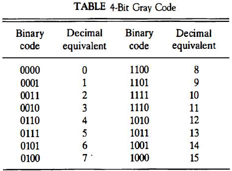
that control the operations in a digital system.A Gray code counter is a counter whose flip-flops go through a sequence of states as specified in Table above. Gray code counters remove the ambiguity during the change from one state of the counter to the next because only one bit can change during the state transition.
Other Decimal Codes
Binary codes for decimal digits require a minimum of four bits. Numerous different codes can be formulated by arranging four or more bits in 10 distinct possible combinations. A few possibilities are shown in Table below.
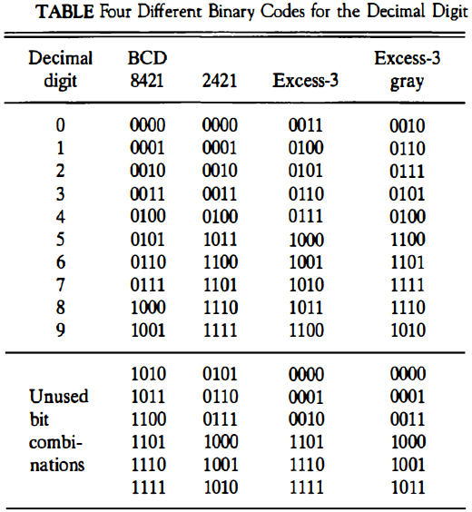
The BCD (binary-coded decimal) uses a straight assignment of the binary equivalent of the digit.
The six unused bit combinations listed have no meaning when BCD is used, just as the letter H has no meaning when decimal digit symbols are written down.
For example, saying that 1001 1110 is a decimal number in BCD is like saying that 9H is a decimal number in the conventional symbol designation. Both cases contain an invalid symbol and therefore designate a meaningless number.
One disadvantage of using BCD is the difficulty encountered when the 9's complement of the number is to be computed. On the other hand, the 9's complement is easily obtained with the 2421 and the excess-3 codes listed self-complementing in Table above. These two codes have a self-complementing property which means that the 9' s complement of a decimal number, when represented in one of these codes, is easily obtained by changing 1's to 0's and 0's to 1's.
This property is useful when arithmetic operations are done in signed-complement representation. weighted code The 2421 is an example of a weighted code. In a weighted code, the bits are multiplied by the weights indicated and the sum of the weighted bits gives the decimal digit.
For example, the bit combination 1101, when weighted by the respective digits 2421, gives the decimal equivalent of 2 x 1 + 4 x 1 + 2 x 0 + 1 + 1 = 7. The BCD code can be assigned the weights 8421 and for this reason it is sometimes called the 8421 code.
The excess-3 code is a decimal code that has been used in older computers. This is an unweighted code. Its binary code assignment is obtained from the corresponding BCD equivalent binary number after the addition of binary 3 (0011).
From Table in gray code section we note that the Gray code is not suited for a decimal code if we were to choose the first 10 entries in the table. This is because the transition from 9 back to 0 involves a change of three bits (from 1101 to 0000). To overcome this difficulty, we choose the 10 numbers starting from the third entry 0010 up to the twelfth entry 1010.
Now the transition from 1010 to 0010 involves a change of only one bit. Since the code has been shifted up three numbers, it is called the excess-3 Gray. This code is listed with the other decimal codes in Table above.
Other Alphanumeric Codes
The ASCII code (Table below) is the standard code commonly used for the transmission of binary information.
Each character is represented by a 7-bit code and usually an eighth bit is inserted for parity. The code consists of 128 characters. Ninety-five characters represent graphic symbols that include upper- and lowercase letters, numerals zero to nine, punctuation marks, and special symbols.
Twenty-three characters represent format effectors, which are functional characters for controlling the layout of printing or display devices such as carriage return, line feed, horizontal tabulation, and back space. The other 10 characters are used to direct the data communication flow and report its status.
-
Another alphanumeric (sometimes called alphameric) code used in IBM equipment is the EBCDIC (Extended BCD Interchange Code). It uses eight bits for each character (and a ninth bit for parity).
EBCDIC has the same character symbols as ASCII but the bit assignment to characters is different.
When alphanumeric characters are used internally in a computer for data processing (not for transmission purposes) it is more convenient to use a 6-bit code to represent 64 characters.
A 6-bit code can specify the 26 uppercase letters of the alphabet, numerals zero to nine, and up to 28 special characters.
This set of characters is usually sufficient for data-processing purposes.
Using fewer bits to code characters has the advantage of reducing the memory space needed to store large quantities of alphanumeric data.
Error Detection Codes
Binary information transmitted through some form of communication medium is subject to external noise that could change bits from 1 to 0, and vice versa.
An error detection code is a binary code that detects digital errors during transmission. The detected errors cannot be corrected but their presence is indicated.
The usual procedure is to observe the frequency of errors. If errors occur infrequently at random, the particular erroneous information is transmitted again. If the error occurs too often, the system is checked for malfunction. The most common error detection code used is the parity bit.
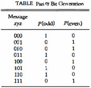
A parity bit is an extra bit included with a binary message to make the total number of 1's either odd or even. A message of three bits and two possible parity bits is shown in Table below.
The P(odd) bit is chosen in such a way as to make the sum of 1's (in all four bits) odd. The P(even) bit is chosen to make the sum of all 1's even. In either case, the sum is taken over the message and the P bit.
In any particular application, one or the other type of parity will be adopted. The even-parity scheme has the disadvantage of having a bit combination of all 0's, while in the odd parity there is always one bit (of the four bits that constitute the message and P) that is 1.
Note that the P(odd) is the complement of the P(even). During transfer of information from one location to another, the parity bit is handled as follows. At the sending end, the message (in this case three bits) is applied to a parity generator, where the required parity bit is generated.
The message, including the parity bit, is transmitted to its destination. At the receiving end, all the incoming bits (in this case, four) are applied to a parity checker that checks the proper parity adopted (odd or even).
An error is detected if the checked parity does not conform to the adopted parity. The parity method detects the presence of one, three, or any odd number of errors. An even number of errors is not detected.
Parity generator and checker networks are logic circuits constructed with exclusive-OR functions. This is because the exclusive-OR function of three or more variables is by definition an odd function.
An odd function is a logic function whose value is binary 1 if, and only if, an odd function number of variables are equal to 1.
According to this definition, the P( even) is the exclusive-OR of x, y and z because it is equal to 1 when either one or all three of the variables are equal to 1 (Table above).
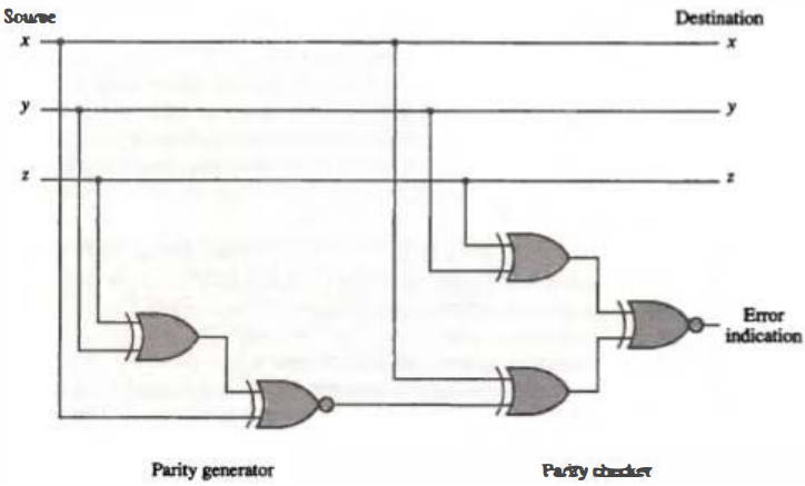
The P(odd) function is the complement of the P(even) function. As an example, consider a 3-bit message to be transmitted with an odd parity bit.
At the sending end, the odd parity bit is generated by a parity generator circuit. As shown in Fig. below, this circuit consists of one exclusive-OR and one exclusive-NOR gate.
Since P(even) is the exclusive-OR of x, y, z, and P(odd) is the complement of P(even), it is necessary to employ an exclusive NOR gate for the needed complementation.
The message and the odd-parity bit are transmitted to their destination where they are applied to a parity checker. An error has occurred during transmission if the parity of the four bits received is even, since the binary information transmitted was originally odd.
The output of the parity checker would be 1 when an error occurs, that is, when the number of 1's in the four inputs is even. Since the exclusive-OR function of the four inputs is an odd function, we again need to complement the output by using an exclusive-NOR gate
It is worth noting that the parity generator can use the same circuit as the parity checker if the fourth input is permanently held at a logic-0 value.
The advantage of this is that the same circuit can be used for both parity generation and parity checking.
It is evident from the example above that even-parity generators and checkers can be implemented with exclusive-OR functions. Odd-parity networks need an exclusive-NOR at the output to complement the function.