Basic Computer Organization and Design
The organization of the computer is defined by its internal registers, timing and control structures, and the sets of instructions it uses.
The internal organization of a digital system is defined by the sequence of micro-operations it performs on data stored in its registers.
The general purpose computer is capable of executing various micro-operations and can be instructed as to what specific sequence of operations it must perform. The user of a computer can control the process by means of a program.
A program is a set of instructions that specify the operations operands, and the sequence by which processing has to occur. The dataprocessing task may be altered by specifying a new program with different instructions or specifying the same instructions with different data.
A computer instruction is a binary code that specifies a sequence of microoperations for the computer. Instruction codes together with data are stored in memory. The computer reads each instruction from memory and places it in a control register.
The control then interprets the binary code of the instruction and proceeds to execute it by issuing a sequence of microoperations. Every computer has its own unique instruction set.
The ability to store and execute instructions, the stored program concept, is the most important property of a general-purpose computer.
An instruction code is a group of bits that instruct the computer to perform a specific operation. It is divided into parts, each having its own particular interpretation.
The most basic part of an instruction code is its operation part. The operation code of an instruction is a group of bits that define such operations as add, subtract, multiply, shift, and complement. The number of bits required for the operation code of an instruction depends on the total number of operations available in the computer.
The operation code must consist of at least n bits for a given 2n (or less) distinct operations. As an illustration, consider a computer with 64 distinct operations, one of them being an ADD operation.
The operation code consists of six bits, with a bit configuration 110010 assigned to the ADD operation . When this operation code is decoded in the control unit, the computer issues control signals to read an operand from memory and add the operand to a processor register.
The relationship between a computer operation and a microoperation is given next. An operation is part of an instruction stored in computer memory.
It is a binary code that tells the computer to perform a specific operation. The control unit receives the instruction from memory and interprets the operation code bits.
It then issues a sequence of control signals to initiate microoperations in internal computer registers. For every operation code, the control issues a sequence of microoperations needed for the hardware implementation of the specified operation.
For this reason, an operation code is sometimes called a macrooperation because it specifies a set of microoperations.
The operation part of an instruction code specifies the operation to be performed. This operation must be performed on some data stored in processor registers or in memory.
An instruction code must therefore specify not only the operation but also the registers or the memory words where the operands are to be found, as well as the register or memory word where the result is to be stored.
Memory words can be specified in instruction codes by their address. Processor registers can be specified by assigning to the instruction another binary code of k bits that specifies one of 2k registers.
There are many variations for arranging the binary code of instructions, and each computer has its own particular instruction code format. Instruction code formats are conceived by computer designers who specify the architecture of the computer.
Stored Program Organization
The simplest way to organize a computer is to have one processor register and an instruction code format with two parts.
The first part specifies the operation to be performed and the second specifies an address.
The memory address tells the control where to find an operand in memory.
This operand is read from memory and used as the data to be operated on together with the data stored in the processor register.
Figure below depicts this type of organization. Instructions are stored in one section of memory and data in another. For a memory unit with 4096 words we need 12 bits to specify an address since 212 = 4096. If we store each instruction code in one 16-bit memory word, we have available four bits for the operation code (abbreviated opcode) to specify one out of 16 possible operations, and 12 bits to specify the address of an operand.
The control reads a 16-bit instruction from the program portion of memory. It uses the 12-bit address part of the instruction to read a 16-bit operand from the data portion of memory.
It then executes the operation specified by the operation code.
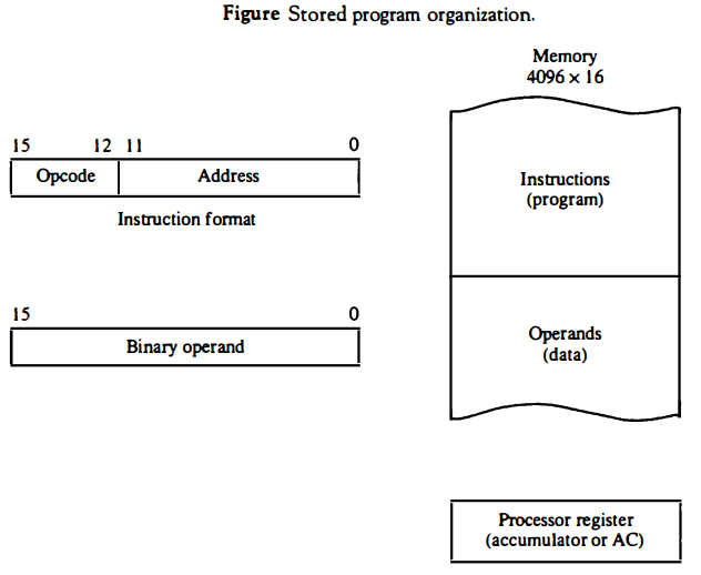
Computers that have a single-processor register usually assign to it the name accumulator and label it AC. The operation is performed with the memory operand and the content of AC.
If an operation in an instruction code does not need an operand from memory, the rest of the bits in the instruction can be used for other purposes. For example, operations such as clear AC, complement AC, and increment AC operate on data stored in the AC register.
They do not need an operand from memory. For these types of operations, the second part of the instruction code (bits 0 through 11) is not needed for specifying a memory address and can be used to specify other operations for the computer.
Indirect Address
It is sometimes convenient to use the address bits of an instruction code not as an address but as the actual operand.
When the second part of an instruction code specifies an operand, the instruction is said to have an immediate operand.
When the second part specifies the address of an operand, the instruction is said to have a direct address.
This is in contrast to a third possibility called indirect address, where the bits in the second part of the instruction designate an address of a memory word in which the address of the operand is found.
One bit of the instruction code can be used to distinguish between a direct and an indirect address.
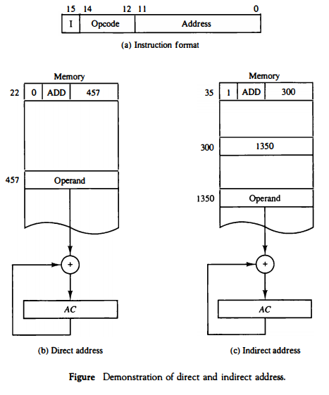
As an illustration of this configuration, consider the instruction code format shown in Fig. below part (a). It consists of a 3-bit operation code, a 12-bit address, and an indirect address mode bit designated by I.
The mode bit is 0 for a direct address and 1 for an indirect address. A direct address instruction is shown in Fig. below part (b). It is placed in address 22 in memory.
The I bit is 0, so the instruction is recognized as a direct address instruction. The opcode specifies an ADD instruction, and the address part is the binary equivalent of 457.
The control finds the operand in memory at address 457 and adds it to the content of AC. The instruction in address 35 shown in Fig. below part (c) has a mode bit I = 1.
Therefore, it is recognized as an indirect address instruction. The address part is the binary equivalent of 300. The control goes to address 300 to find the address of the operand.
The address of the operand in this case is 1350. The operand found in address 1350 is then added to the content of AC. The indirect address instruction needs two references to memory to fetch an operand. The first reference is needed to read the address of the operand; the second is for the operand itself.
We define the effective address to be the address of the operand in a computation-type instruction or the target address in a branch-type instruction.
Thus the effective address in the instruction of Fig. below part (b) is 457 and in the instruction of Fig below part (c) is 1350.
The direct and indirect addressing modes are used in the computer presented in this chapter.
The memory word that holds the address of the operand in an indirect address instruction is used as a pointer to an array of data. The pointer could be placed in a processor register instead of memory as done in commercial computers.
Computer Registers
Computer instructions are normally stored in consecutive memory locations and are executed sequentially one at a time.
The control reads an instruction from a specific address in memory and executes it. It then continues by reading the next instruction in sequence and executes it, and so on.
This type of instruction sequencing needs a counter to calculate the address of the next instruction after execution of the current instruction is completed.
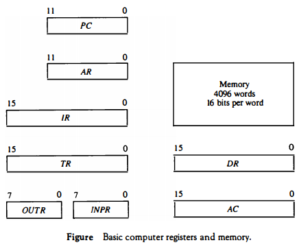
It is also necessary to provide a register in the control unit for storing the instruction code after it is read from memory. The computer needs processor registers for manipulating data and a register for holding a memory address. These requirements dictate the register configuration shown in Fig. below.
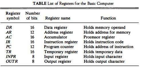
The registers are also listed in Table below together with a brief description of their function and the number of bits that they contain.
The memory unit has a capacity of 4096 words and each word contains 16 bits. Twelve bits of an instruction word are needed to specify the address of an operand.
This leaves three bits for the operation part of the instruction and a bit to specify a direct or indirect address. The data register (DR) holds the operand read from memory.
The accumulator (AC) register is a general purpose processing register. The instruction read from memory is placed in the instruction register (IR). The temporary register (TR) is used for holding temporary data during the processing.
The memory address register (AR) has 12 bits since this is the width of a memory address. The program counter (PC) also has 12 bits and it holds the address of the next instruction to be read from memory after the current instruction is executed.
The PC goes through a counting sequence and causes the computer to read sequential instructions previously stored in memory. Instruction words are read and executed in sequence unless a branch instruction is encountered.
A branch instruction calls for a transfer to a nonconsecutive instruction in the program.
The address part of a branch instruction is transferred to PC to become the address of the next instruction. To read an instruction, the content of PC is taken as the address for memory and a memory read cycle is initiated.
PC is then incremented by one, so it holds the address of the next instruction in sequence.
Two registers are used for input and output. The input register (INPR) receives an 8-bit character from an input device. The output register (OUTR) holds an 8-bit character for an output device.