Addressing Modes
The operation field of an instruction specifies the operation to be performed.
This operation must be executed on some data stored in computer registers or memory words.
The way the operands are chosen during program execution is dependent on the addressing mode of the instruction. The addressing mode specifies a rule for interpreting or modifying the address field of the instruction before the operand is actually referenced.
Computers use addressing mode techniques for the purpose of accommodating one or both of the following provisions:
To give programming versatility to the user by providing such facilities as pointers to memory, counters for loop control, indexing of data, and program relocation.
To reduce the number of bits in the addressing field of the instruction.
The availability of the addressing modes gives the experienced assembly language programmer flexibility for writing programs that are more efficient with respect to the number of instructions and execution time.
To understand the various addressing modes to be presented in this section, it is imperative that we understand the basic operation cycle of the computer.
The control unit of a computer is designed to go through an instruction cycle that is divided into three major phases:
1. Fetch the instruction from memory.
2. Decode the instruction.
3. Execute the instruction.
There is one register in the computer called the program counter or PC that keeps track of the instructions in the program stored in memory. PC holds the address of the instruction to be executed next and is incremented each time an instruction is fetched from memory.
The decoding done in step 2 determines the operation to be performed, the addressing mode of the instruction, and the location of the operands. The computer then executes the instruction and returns to step 1 to fetch the next instruction in sequence.
In some computers the addressing mode of the instruction is specified with a distinct binary code, just like the operation code is specified. Other computers use a single binary code that designates both the operation and the mode of the instruction.
Instructions may be defined with a variety of addressing modes, and sometimes, two or more addressing modes are combined in one instruction.
An example of an instruction format with a distinct addressing mode field is shown in Fig. 6. The operation code specifies the operation to be permode field formed. The mode field is used to locate the operands needed for the operation.
There may or may not be an address field in the instruction. If there is an address field, it may designate a memory address or a processor register.
Moreover, as discussed in the preceding section, the instruction may have more than one address field, and each address field may be associated with its own particular addressing mode.
Although most addressing modes modify the address field of the instruction, there are two modes that need no address field at all. These are the implied and immediate modes.
Implied Mode
In this mode the operands are specified implicitly in the definition of the instruction.
For example, the instruction "complement accumulator" is an implied-mode instruction because the operand in the accumulator register is implied in the definition of the instruction.
In fact, all register reference instructions that use an accumulator are implied-mode instructions.
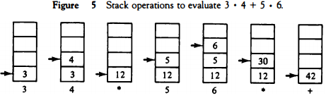
Zero-address instructions in a stack-organized computer are implied-mode instructions since the operands are implied to be on top of the stack.
Immediate Mode
In this mode the operand is specified in the instruction itself. In other words, an immediate-mode instruction has an operand field rather than an address field.
The operand field contains the actual operand to be used in conjunction with the operation specified in the instruction. Immediate-mode instructions are useful for initializing registers to a constant value.
It was mentioned previously that the address field of an instruction may specify either a memory word or a processor register.
When the address field specifies a processor register, the instruction is said to be in the register mode.
Register Mode
In this mode the operands are in registers that reside within the CPU. The particular register is selected from a register field in the instruction.
A k-bit field can specify any one of 2k registers.
Register Indirect Mode
In this mode the instruction specifies a register in the CPU whose contents give the address of the operand in memory. In other words, the selected register contains the address of the operand rather than the operand itself.
Before using a register indirect mode instruction, the programmer must ensure that the memory address of the operand is placed in the processor register with a previous instruction.
A reference to the register is then equivalent to specifying a memory address.
The advantage of a register indirect mode instruction is that the address field of the instruction uses fewer bits to select a register than would have been required to specify a memory address directly.
Autoincrement or Autodecrement Mode
This is similar to the register indirect mode except that the register is incremented or decremented after (or before) its value is used to access memory.
When the address stored in the register refers to a table of data in memory, it is necessary to increment or decrement the register after every access to the table.
This can be achieved by using the increment or decrement instruction.
However, because it is such a common requirement, some computers incorporate a special mode that automatically increments or decrements the content of the register after data access. The address field of an instruction is used by the control unit in the CPU to obtain the operand from memory.
Sometimes the value given in the address field is the address of the operand, but sometimes it is just an address from which the address of the operand is calculated.
To differentiate among the various addressing modes it is necessary to distinguish between the address part of the instruction and the effective address used by the control when executing the instruction.
The effective address is defined to be the memory address obtained from the computation dictated by the given addressing mode. The effective address is the address of the operand in a computational- type instruction.
It is the address where control branches in response to a branch-type instruction.
Direct Address Mode
In this mode the effective address is equal to the address part of the instruction.
The operand resides in memory and its address is given directly by the address field of the instruction.
In a branch-type instruction the address field specifies the actual branch address.
Indirect Address Mode
In this mode the address field of the instruction gives the address where the effective address is stored in memory.
Control fetches the instruction from memory and uses its address part to access memory again to read the effective address.
A few addressing modes require that the address field of the instruction be added to the content of a specific register in the CPU.
The effective address in these modes is obtained from the following computation: effective address = address part of instruction + content of CPU register
The CPU register used in the computation may be the program counter, an index register, or a base register.
In either case we have a different addressing mode which is used for a different application.
Relative Address Mode
In this mode the content of the program counter is added to the address part of the instruction in order to obtain the effective address.
The address part of the instruction is usually a signed number (in 2' s complement representation) which can be either positive or negative. When this number is added to the content of the program counter, the result produces an effective address whose position in memory is relative to the address of the next instruction.
To clarify with an example, assume that the program counter contains the number 825 and the address part of the instruction contains the number 24.
The instruction at location 825 is read from memory during the fetch phase and the program counter is then incremented by one to 826. The effective address computation for the relative address mode is 826 + 24 = 850.
This is 24 memory locations forward from the address of the next instruction. Relative addressing is often used with branch-type instructions when the branch address is in the area surrounding the instruction word itself.
It results in a shorter address field in the instruction format since the relative address can be specified with a smaller number of bits compared to the number of bits required to designate the entire memory address.
Indexed Addressing Mode
In this mode the content of an index register is added to the address part of the instruction to obtain the effective address.
The index register is a special CPU register that contains an index value.
The address field of the instruction defines the beginning address of a data array in memory.
Each operand in the array is stored in memory relative to the beginning address. The distance between the beginning address and the address of the operand is the index value stored in the index register.
Any operand in the array can be accessed with the same instruction provided that the index register contains the correct index value.
The index register can be incremented to facilitate access to consecutive operands. Note that if an indextype instruction does not include an address field in its format, the instruction converts to the register indirect mode of operation.
Some computers dedicate one CPU register to function solely as an index register.
This register is involved implicitly when the index-mode instruction is used.
In computers with many processor registers, any one of the CPU registers can contain the index number.
In such a case the register must be specified explicitly in a register field within the instruction format.
Base Register Addressing Mode
In this mode the content of a base register is added to the address part of the instruction to obtain the effective address.
This is similar to the indexed addressing mode except that the register is now called a base register instead of an index register.
The difference between the two modes is in the way they are used rather than in the way that they are computed. An index register is assumed to hold an index number that is relative to the address part of the instruction.
A base register is assumed to hold a base address and the address field of the instruction gives a displacement relative to this base address. The base register addressing mode is used in computers to facilitate the relocation of programs in memory.
When programs and data are moved from one segment of memory to another, as required in multiprogramming systems, the address values of instructions must reflect this change of position.
With a base register, the displacement values of instructions do not have to change. Only the value of the base register requires updating to reflect the beginning of a new memory segment.
Numerical Example
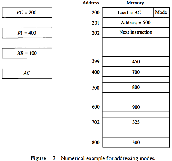
To show the differences between the various modes, we will show the effect of the addressing modes on the instruction defined in Fig. 7.
The two-word instruction at address 200 and 201 is a "load to AC" instruction with an address field equal to 500.
The first word of the instruction specifies the operation code and mode, and the second word specifies the address part.
PC has the value 200 for fetching this instruction. The content of processor register R1 is 400, and the content of an index register XR is 100.
AC receives the operand after the instruction is executed. The figure lists a few pertinent addresses and shows the memory content at each of these addresses.
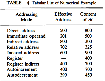
The mode field of the instruction can specify any one of a number of modes. For each possible mode we calculate the effective address and the operand that must be loaded into AC.
In the direct address mode the effective address is the address part of the instruction 500 and the operand to be loaded into AC is 800. In the immediate mode the second word of the instruction is taken as the operand rather than an address, so 500 is loaded into AC. (The effective address in this case is 201 .)
In the indirect mode the effective address is stored in memory at address 500. Therefore, the effective address is 800 and the operand is 300. In the relative mode the effective address is 500 + 202 = 702 and the operand is 325.
(Note that the value in PC after the fetch phase and during the execute phase is 202.) In the index mode the effective address is XR + 500 = 100 + 500 = 600 and the operand is 900. In the register mode the operand is in R1 and 400 is loaded into AC.
(There is no effective address in this case.) In the register indirect mode the effective address is 400, equal to the content of R1 and the operand loaded into AC is 700.
The autoincrement mode is the same as the register indirect mode except that R1 is incremented to 401 after the execution of the instruction. The autodecrement mode decrements R1 to 399 prior to the execution of the instruction.
The operand loaded into AC is now 450. Table 4 lists the values of the effective address and the operand loaded into AC for the nine addressing modes.