Parallel Processing
Parallel processing is a term used to denote a large class of techniques that are used to provide simultaneous data-processing tasks for the purpose of inaeasing the computational speed of a computer system.
Instead of processing each instruction sequentially as in a conventional computer, a parallel processing system is able to perform concurrent data processing to achieve faster execution time.
For example, while an instruction is being executed in the ALU, the next instruction can be read from memory.
The system may have two or more ALUs and be able to execute two or more instructions at the same time.
Furthermore, the system may have two or more processors operating concurrently.
The purpose of parallel processing is to speed up the computer processing capability and increase its throughput, that is, the amount of processing that can be accomplished during a given interval of time.
The amount of hardware increases with parallel processing and with it, the cost of the system increases.
However, technological developments have reduced hardware costs to the point where parallel processing techniques are economically feasible.
We distinguish between parallel and serial operations by the type of registers used. Shift registers operate in serial fashion one bit at a time, while registers with parallel load operate with all the bits of the word simultaneously
Figure 1 shows one possible way of separating the execution unit into eight functional units operating in parallel. The operands in the registers are applied to one of the units depending on the operation specified by the instruction associated with the operands
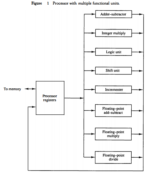
All units are independent of each other, so one number can be shifted while another number is being incremented.
A multifunctional organization is usually associated with a complex control unit to coordinate all the activities among the various components.
Classification of Parallel Processing
One classification introduced by M. J. Flynn considers the organization of a computer system by the number of instructions and data items that are manipulated simultaneously. The normal operation of a computer is to fetch instructions from memory and execute them in the processor.
The sequence of instructions read from memory constitutes an instruction stream . The operations performed on the data in the processor constitutes a data stream .
Parallel processing may occur in the instruction stream, in the data stream, or in both. Flynn's classification divides computers into four major groups as follows:
Single instruction stream, single data stream (SISD)
Single instruction stream, multiple data stream (SIMD)
Multiple instruction stream, single data stream (MISD)
Multiple instruction stream, multiple data stream (MIMD)
SISD represents the organization of a single computer containing a control unit, a processor unit, and a memory unit.
Instructions are executed sequentially and the system may or may not have internal parallel processing capabilities.
Parallel processing in this case may be achieved by means of multiple functional units or by pipeline processing.
SIMD represents an organization that includes many processing units under the supervision of a common control unit.
All processors receive the same instruction from the control unit but operate on different items of data. The shared memory unit must contain multiple modules so that it can communicate with all the processors simultaneously.
MISD structure is only of theoretical interest since no practical system has been constructed using this organization.
MIMD organization refers to a computer system capable of processing several programs at the same time. Most multiprocessor and multicomputer systems can be classified in this category.
Flynn's classification depends on the distinction between the performance of the control unit and the data-processing unit.
It emphasizes the behavioral characteristics of the computer system rather than its operational and structural interconnections.
Pipelining
Pipelining is a technique of decomposing a sequential process into suboperations, with each subprocess being executed in a special dedicated segment that operates concurrently with all other segments.
A pipeline can be visualized as a collection of processing segments through which binary information flows. Each segment performs partial processing dictated by the way the task is partitioned.
The result obtained from the computation in each segment is transferred to the next segmentin the pipeline. The final result is obtained after the data have passed through all segments.
The name "pipeline" implies a flow of information analogous to an industrial assembly line.
It is characteristic of pipelines that several computations can be in progress in distinct segments at the same time. The overlapping of computation is made possible by associating a register with each segment in the pipeline.
The registers provide isolation between each segment so that each can operate on distinct data simultaneously.
Perhaps the simplest way of viewing the pipeline structure is to imagine that each segment consists of an input register followed by a combinational circuit. The register holds the data and the combinational circuit performs the suboperation in the particular segment.
The output of the combinational circuit in a given segment is applied to the input register of the next segment. A clock is applied to all registers after enough time has elapsed to perform all segment activity. In this way the information flows through the pipeline one step at a time.
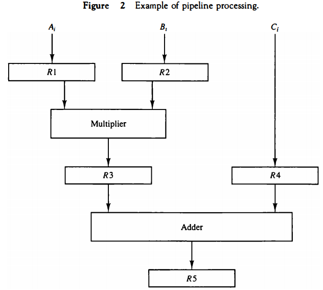
The pipeline organization will be demonstrated by means of a simple example. Suppose that we want to perform the combined multiply and add operations with a stream of numbers. Ai * Bi + Ci for i = 1, 2, 3, . .. , 7
Each suboperation is to be implemented in a segment within a pipeline. Each segment has one or two registers and a combinational circuit as shown in Fig. 2. R1 through R5 are registers that receive new data with every clock pulse. The multiplier and adder are combinational circuits. The suboperations performed in each segment of the pipeline are as follows:
R1 ← Ai, R2 ← Bi Input Ai and Bi R3 ← R1 * R2, R4 ← Ci Multiply and input Ci R5 ← R3 + R4 Add Ci to product
The five registers are loaded with new data every clock pulse. The effect of each clock is shown in Table 1. The first clock pulse transfers A1 and B1 into R1 and R2.
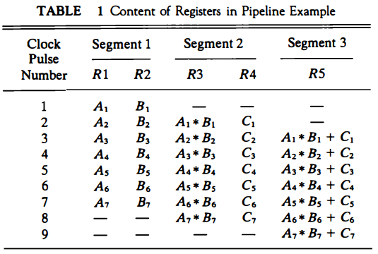
The second dock pulse transfers the product of R1 and R2 into R3 and C1 into R4. The same clock pulse transfers A2 and B2 into R1 and R2. The third clock pulse operates on all three segments simultaneously.
It places A, and B, into R1 and R2, transfers the product of R1 and R2 into R3, transfers C, into R4, and places the sum of R3 and R4 into RS. It takes three clock pulses to fill up the pipe and retrieve the first output from RS. From there on, each dock produces a new output and moves the data one step down the pipeline.
This happens as long as new input data flow into the system. When no more input data are available, the clock must continue until the last output emerges out of the pipeline.
Mathematical Notations for Pipelining
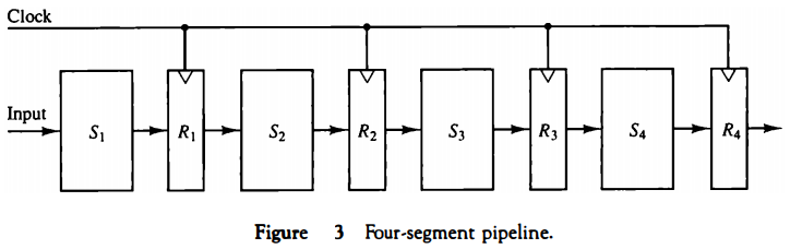
The general structure of a four-segment pipeline is illustrated in Fig. 3. The operands pass through all four segments in a fixed sequence.
Each segment consists of a combinational circuit Si that performs a suboperation over the data stream flowing through the pipe.
The segments are separated by registers Ri that hold the intermediate results between the stages.
Information flows between adjacent stages under the control of a common clock applied to all the registers simultaneously.
We task define a task as the total operation performed going through all the segments in the pipeline.
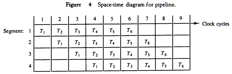
The behavior of a pipeline can be illustrated with a space-time diagram. This is a cliagram that shows the segment utilization as a function of time. The space-time cliagram of a four-segment pipeline is demonstrated in Fig. 4. The horizontal axis clisplays the time in clock cycles and the vertical axis gives the segment number.
The diagram shows six tasks T1 through T6 executed in four segments. Initially, task T1 is handled by segment 1. After the first clock, segment 2 is busy with T1, while segment 1 is busy with task T2.
Continuing in this manner, the first task T1 is completed after the fourth clock cycle.
From then on, the pipe completes a task every clock cycle. No matter how many segments there are in the system, once the pipeline is full, it takes only one clock period to obtain an output.
Now consider the case where a k-segment pipeline with a clock cycle time tp is used to execute n tasks.
The first task T1 requires a time equal to ktp to complete its operation since there are k segments in the pipe. The remaining n - 1 tasks emerge from the pipe at the rate of one task per clock cycle and they will be completed after a time equal to (n - 1)tp.
Therefore, to complete n tasks using a k-segment pipeline requires k + (n - 1) clock cycles. For example, the diagram of Fig. 4 shows four segments and six tasks. The time required to complete all the operations is 4 + (6 - 1) = 9 clock cycles, as indicated in the diagram.
Next consider a nonpipeline unit that performs the same operation and takes a time equal to tn. to complete each task. The total time required for n tasks is ntn.
The speedup of a pipeline processing over an equivalent nonpipeline processing is defined by the ratio \( S = \frac{nt_n}{(k + n - 1)t_p} \)
As the number of tasks increases, n becomes much larger than k - 1, and k + n - 1 approaches the value of n. Under this condition, the speedup becomes \( S = \frac{t_n}{t_p} \)
If we assume that the time it takes to process a task is the same in the pipeline and non pipeline circuits, we will have tn = ktp. Including this assumption, the speedup reduces to \( S = \frac{kt_p}{t_p} = k\)
This shows that the theoretical maximum speedup that a pipeline can provide is k, where k is the number of segments in the pipeline.
To clarify the meaning of the speedup ratio, consider the following numerical example. Let the time it takes to process a suboperation in each segment be equal to tp = 20 ns.
Assume that the pipeline has k = 4 segments and executes n = 100 tasks in sequence. The pipeline system will take (k + n - 1)tp = (4 + 99) x 20 = 2060 ns to complete. Assuming that tn = ktp = 4 x 20 = 80 ns, a non pipeline system requires nktp = 100 x 80 = 8000 ns to complete the 100 tasks.
The speedup ratio is equal to 8000/2060 = 3.88. As the number of tasks increases, the speedup will approach 4, which is equal to the number of segments in the pipeline. If we assume that tn = 60 ns, the speedup becomes 60/20 = 3.
To duplicate the theoretical speed advantage of a pipeline process by means of multiple functional units, it is necessary to construct k identical units that will be operating in parallel.
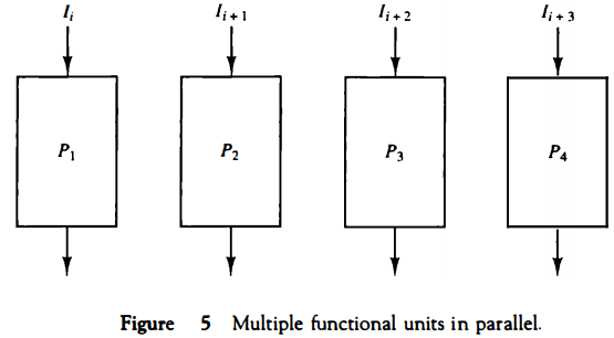
The implication is that a k-segment pipeline processor can be expected to equal the performance of k copies of an equivalent nonpipeline circuit under equal operating conditions. This is illustrated in Fig. 5, where four identical circuits are connected in parallel. Each P circuit performs the same task of an equivalent pipeline circuit.
Instead of operating with the input data in sequence as in a pipeline, the parallel circuits acceptfour input data items simultaneously and perform four tasks at the same time. As far as the speed of operation is concerned, this is equivalent to a four segment pipeline.
Note that the four-unit circuit of Fig. 5 constitutes a single-instruction multiple-data (SIMD) organization since the same instruction is used to operate on multiple data in parallel.
There are various reasons why the pipeline cannot operate at its maximum theoretical rate. Different segments may take different times to complete their suboperation. The clock cycle must be chosen to equal the time delay of the segment with the maximum propagation time.
This causes all other segments to waste time while waiting for the next clock. Moreover, it is not always correct to assume that a nonpipe circuit has the same time delay as that of an equivalent pipeline circuit.
Many of the intermediate registers will not be needed in a single-unit circuit, which can usually be constructed entirely as a combinational circuit.
Nevertheless, the pipeline technique provides a faster operation over a purely serial sequence even though the maximum theoretical speed is never fully achieved.
There are two areas of computer design where the pipeline organization is applicable. An arithmetic pipeline divides an arithmetic operation into suboperations for execution in the pipeline segments.
An instruction pipeline operates on a stream of instructions by overlapping the fetch, decode, and execute phases of the instruction cycle.
Arithmetic Pipeline
Pipeline arithmetic units are usually found in very high speed computers. They are used to implement floating-point operations, multiplication of fixed-point numbers, and similar computations encountered in scientific problems.
A pipeline multiplier is essentially an array multiplier, with special adders designed to minimize the carry propagation time through the partial products.
Floating-point operations are easily decomposed into suboperations.
The inputs to the floating-point adder pipeline are two normalized floating-point binary numbers.
X = A * 2a; Y = B * 2b
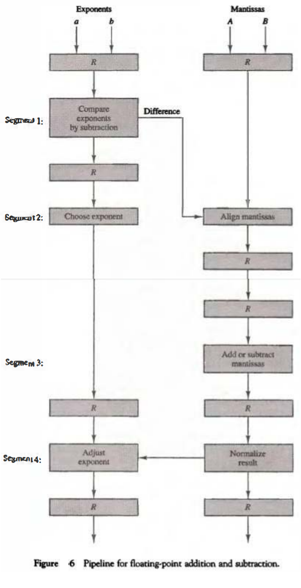
A and B are two fractions that represent the mantissas and a and b are the exponents. The floating-point addition and subtraction can be performed in four segments, as shown in Fig. 6. The registers labeled R are placed between the segments to store intermediate results. The suboperations that are performed in the four segments are:
1. Compare the exponents.
2. Align the mantissas.
3. Add or subtract the mantissas.
4. Normalize the result.
The exponents are compared by subtracting them to determine their difference.
The larger exponent is chosen as the exponent of the result. The exponent difference determines how many times the mantissa associated with the smaller exponent must be shifted to the right.
This produces an alignment of the two mantissas. It should be noted that the shift must be designed as a combinational circuit to reduce the shift time. The two mantissas are added or subtracted in segment 3. The result is normalized in segment 4.
When an overflow occurs, the mantissa of the sum or difference is shifted right and the exponent incremented by one.
If an underflow occurs, the number of leading zeros in the mantissa determines the number of left shifts in the mantissa and the number that must be subtracted from the exponent.
The following numerical example may clarify the suboperations performed in each segment. For simplicity, we use decimal numbers, although Fig. 6 refers to binary numbers. Consider the two normalized floating-point numbers:
X = 0.9504 * 103
Y = 0.8200 * 102
The two exponents are subtracted in the first segment to obtain 3 - 2 = 1. The larger exponent 3 is chosen as the exponent of the result. The next segment shifts the mantissa of Y to the right to obtain
X= 0.9504 * 103
Y = 0.0820 * 103
This aligns the two mantissas under the same exponent. The addition of the two mantissas in segment 3 produces the sum Z = 1 .0324 * 103
The sum is adjusted by normalizing the result so that it has a fraction with a nonzero first digit. This is done by shifting the mantissa once to the right and incrementing the exponent by one to obtain the normalized sum.
Z = 0.10324 * 104
The comparator, shifter, adder-subtractor, incrementer, and decrementer in the floating-point pipeline are implemented with combinational circuits. Suppose thatthe timedelaysof the four segments are t1 = 60 ns, t2 = 70 ns, t3 = 100 ns, t4 = 80 ns, and the interface registers have a delay of tr = 10 ns.
The clock cycle is chosen to be tp = t3 + tr = 110 ns.
An equivalent nonpipeline floatingpoint adder-subtractor will have a delay time tn = t1 + t2 + t3 + t4 + tr = 320 ns.
In this case the pipelined adder has a speedup of 320/110 = 2.9 over the nonpipelined adder.
Instruction Pipeline
Pipeline processing can occur not only in the data stream but in the instruction stream as well.
An instruction pipeline reads consecutive instructions from memory while previous instructions are being executed in other segments. This causes the instruction fetch and execute phases to overlap and perform simultaneous operations.
One possible digression associated with such a scheme is that an instruction may cause a branch out of sequence. In that case the pipeline must be emptied and all the instructions that have been read from memory after the branch instruction must be discarded.
Consider a computer with an instruction fetch unit and an instruction execution unit designed to provide a two-segment pipeline. The instruction fetch segment can be implemented by means of a first-in, first-out (FIFO) buffer. This is a type of unit that forms a queue rather than a stack.
Whenever the execution unit is not using memory, the control increments the program counter and uses its address value to read consecutive instructions from memory. The instructions are inserted into the FIFO buffer so that they can be executed on a first-in, first-out basis.
Thus an instruction stream can be placed in a queue, waiting for decoding and processing by the execution segment. The instruction stream queuing mechanism provides an efficient way for reducing the average access time to memory for reading instructions.
Whenever there is space in the FIFO buffer, the control unit initiates the next instruction fetch phase.
The buffer acts as a queue from which control then extracts the instructions for the execution unit.
Computers with complex instructions require other phases in addition to the fetch and execute to process an instruction completely. In the most general case, the computer needs to process each instruction with the following sequence of steps.
1. Fetch the instruction from memory.
2. Decode the instruction.
3. Calculate the effective address.
4. Fetch the operands from memory.
5. Execute the instruction.
6. Store the result in the proper place.
There are certain difficulties that will prevent the instruction pipeline from operating at its maximum rate. Different segments may take different times to operate on the incoming information.
Some segments are skipped for certain operations. For example, a register mode instruction does not need an effective address calculation.
Two or more segments may require memory access at the same time, causing one segment to wait until another is finished with the memory.
Memory access conflicts are sometimes resolved by using two memory buses for accessing instructions and data in separate modules. ln this way, an instruction word and a data word can be read simultaneously from two different modules.
The design of an instruction pipeline will be most efficient if the instruction cycle is divided into segments of equal duration. The time that each step takes to fulfill its function depends on the instruction and the way itis executed.
Example: Four-Segment Instruction Pipeline
Assume that the decoding of the instruction can be combined with the calculation of the effective address into one segment.
Assume further that most of the instructions place the result into a processor register so that the instruction execution and storing of the result can be combined into one segment. This reduces the instruction pipeline into four segments.
Figure 7 shows how the instruction cycle in the CPU can be processed with a four-segment pipeline. While an instruction is being executed in segment 4, the next instruction in sequence is busy fetching an operand from memory in segment 3.
The effective address may be calculated in a separate arithmetic circuit for the third instruction, and whenever the memory is available, the fourth and all subsequent instructions can be fetched and placed in an instruction FIFO.
Thus up to four suboperations in the instruction cycle can overlap and up to four different instructions can be in progress of being processed at the same time.
Once in a while, an instruction in the sequence may be a program control type that causes a branch out of normal sequence.
In that case the pending operations in the last two segments are completed and all information stored in the instruction buffer is deleted. The pipeline then restarts from the new address stored in the program counter.
Similarly, an interrupt request, when acknowledged, will cause the pipeline to empty and start again from a new address value.
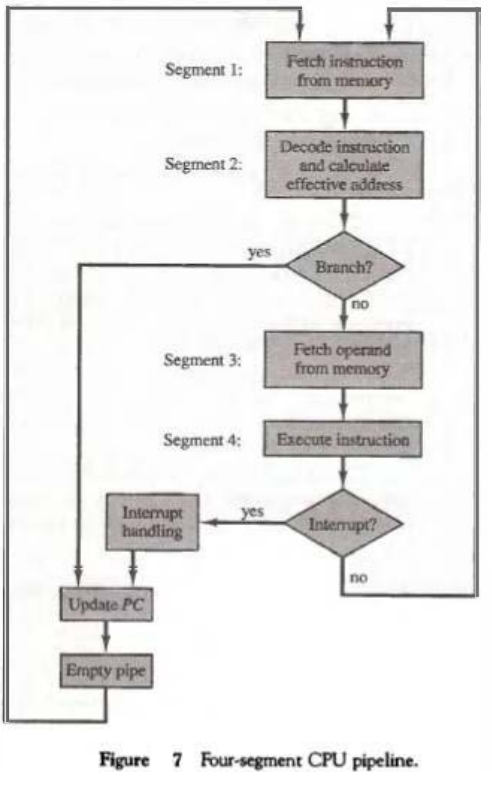 Figure 8 shows the operation of the instruction pipetine. The time in the horizontal
axis is divided into steps of equal duration. The four segments are
represented in the diagram with an abbreviated symbol.
Figure 8 shows the operation of the instruction pipetine. The time in the horizontal
axis is divided into steps of equal duration. The four segments are
represented in the diagram with an abbreviated symbol.1. F1 is the segment that fetches an instruction. 2. DA is the segment that decodes the instruction and calculates the effective address. 3. FO is the segment that fetches the operand. 4. EX is the segment that executes the instruction.
It is assumed that the processor has separate instruction and data memories so that the operation in Fl and FO can proceed at the same time. In the absence
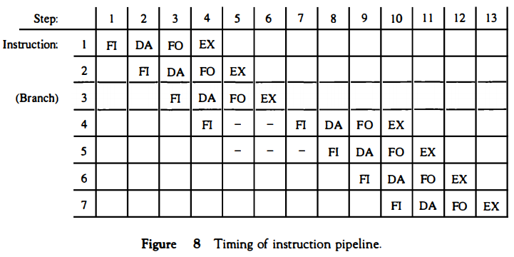 of a branch instruction, each segment operates on different instructions.
 Thus, in step 4, instruction 1 is being executed in segment EX; the operand for instruction 2 is being fetched in segment FO; instruction 3 is being decoded in segment DA; and instruction 4 is being fetched from memory in segment FL Assume now that instruction 3 is a branch instruction.
As soon as this instruction is decoded in segment DA in step 4, the transfer from FI to DA of the other instructions is halted until the branch instruction is executed in step 6. If the branch is taken, a new instruction is fetched in step 7.
If the branch is not taken, the instruction fetched previously in step 4 can be used. The pipeline then continues until a new branch instruction is encountered. Another delay may occur in the pipeline if the EX segment needs to store the result of the operation in the data memory while the FO segment needs to fetch an operand. In that case, segment FO must wait until segment EX has finished its operation.
In general, there are three major difficulties that cause the instruction pipeline to deviate from its normal operation.
1. Resource conflicts caused by access to memory by two segments at the
same time. Most of these conflicts can be resolved by using separate
instruction and data memories.
2. Data dependency conflicts arise when an instruction depends on the
result of a previous instruction, but this result is not yet available.
3. Branch difficulties arise from branch and other instructions that change
the value of PC.