Asynchronous Data Transfer
The internal operations in a digital system are synchronized by means of clock pulses supplied by a common pulse generator.
Clock pulses are applied to all registers within a unit and all data transfers among internal registers occur simultaneously during the occurrence of a clock pulse.
Two units, such as a CPU and an I/O interface, are designed independently of each other.
If the registers in the interface share a common clock with the CPU registers, the transfer between the two units is said to be synchronous.
In most cases, the internal timing in each unit is independent from the other in that each uses its own private clock for internal registers. In that case, the two units are said to be asynchronous to each other. This approach is widely used in most computer systems.
Asynchronous data transfer between two independent units requires that control signals be transmitted between the communicating units to indicate the time at which data is being transmitted.
One way of achieving this is by means of a strobe pulse supplied by one of the units to indicate to the other unit when the transfer has to occur.
Another method commonly used is to accompany each data item being transferred with a control signal that indicates the presence of data in the bus.
The unit receiving the data item responds with another control signal to acknowledge receipt of the data. This type of agreement between two independent units is referred to as handshaking.
The strobe pulse method and the handshaking method of asynchronous data transfer are not restricted to I/O transfers. In fact, they are used extensively on numerous occasions requiring the transfer of data between two independent units.
In the general case we consider the transmitting unit as the source and the receiving unit as the destination.
For example, the CPU is the source unit during an output or a write transfer and it is the destination unit during an input or a read transfer.
It is customary to specify the asynchronous transfer between two independent units by means of a timing diagram that shows the timing relationship that must exist between the control signals and the data in the buses.
The sequence of control during an asynchronous transfer depends on whether the transfer is initiated by the source or by the destination unit.
Strobe Control
The strobe control method of asynchronous data transfer employs a single control line to time each transfer. The strobe may be activated by either the source or the destination unit. Figure 3(a) shows a source-initiated transfer.
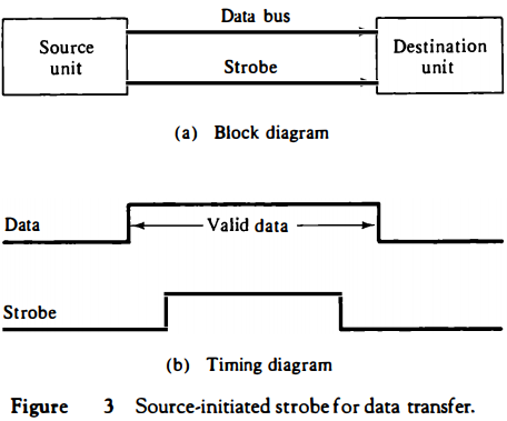
The data bus carries the binary information from source unit to the destination unit.
Typically, the bus has multiple lines to transfer an entire byte or word. The strobe is a single line that informs the destination unit when a valid data word is available in the bus.
As shown in the timing diagram of Fig. 3(b), the source unit first places the data on the data bus.
After a brief delay to ensure that the data settle to a steady value, the source activates the strobe pulse.
The information on the data bus and the strobe signal remain in the active state for a sufficient time period to allow the destination unit to receive the data.
Often, the destination unit uses the falling edge of the strobe pulse to transfer the contents of the data bus into one of its internal registers.
The source removes the data from the bus a brief period after it disables its strobe pulse.
Actually, the source does not have to change the information in the data bus. The fact that the strobe signal is disabled indicates that the data bus does not contain valid data. New valid data will be available only after the strobe is enabled again.
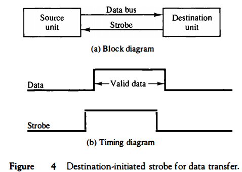
Figure 4 shows a data transfer initiated by the destination unit. In this case the destination unit activates the strobe pulse, informing the source to provide the data.
The source unit responds by placing the requested binary information on the data bus. The data must be valid and remain in the bus long enough for the destination unit to accept it. The falling edge of the strobe pulse can be used again to trigger a destination register
The destination unit then disables the strobe. The source removes the data from the bus after a predetermined time interval.
In many computers the strobe pulse is actually controlled by the clock pulses in the CPU. The CPU is always in control of the buses and informs the external units how to transfer data.
For example, the strobe of Fig. 3 could be a memory-write control signal from the CPU to a memory unit. The source, being the CPU, places a word on the data bus and informs the memory unit, which is the destination, that this is a write operation.
Similarly, the strobe of Fig. 4 could be a memory-read control signal from the CPU to a memory unit.
The destination, the CPU, initiates the read operation to inform the memory, which is the source, to place a selected word into the data bus.
The transfer of data between the CPU and an interface unit is similar to the strobe transfer just described.
Data transfer between an interface and an I/O device is commonly controlled by a set of handshaking lines.
Handshaking
The disadvantage of the strobe method is that the source unit that initiates the transfer has no way of knowing whether the destination unit has actually received the data item that was placed in the bus.
Similarly, a destination unit that initiates the transfer has no way of knowing whether the source unit has actually placed the data on the bus.
The handshake method solves this problem by introducing a second control signal that provides a reply to the unit that initiates the transfer.
The basic principle of the two-wire handshaking method of data transfer is as follows.
One control line is in the same direction as the data flow in the bus from the source to the destination.
It is used by the source unit to inform the destination unit whether there are valid data in the bus.
The other control line is in the other direction from the destination to the source.
It is used by the destination unit to inform the source whether it can accept data. The sequence of control during the transfer depends on the unit that initiates the transfer.
Figure 5 shows the data transfer procedure when initiated by the source. The two handshaking lines are data valid, which is generated by the source unit, and data accepted, generated by the destination unit.
The timing diagram shows the exchange of signals between the two units. The sequence of events listed in part (c) shows the four possible states that the system can be at any given time.
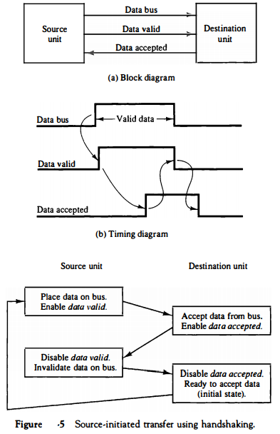
The source unit initiates the transfer by placing the data on the bus and enabling its data valid signal.
The data accepted signal is activated by the destination unit after it accepts the data from the bus.
The source unit then disables its data valid signal, which invalidates the data on the bus.
The destination unit then disables its data accepted signal and the system goes into its initial state.
The source does not send the next data item until after the destination unit shows its readiness to accept new data by disabling its data accepted signal.
This scheme allows arbitrary delays from one state to the next and permits each unit to respond at its own data transfer rate. The rate of transfer is determined by the slowest unit.
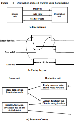
The destination-initiated transfer using handshaking lines is shown in Fig. 6. Note that the name of the signal generated by the destination unit has been changed to ready for data to reflect its new meaning.
The source unit in this case does not place data on the bus until after it receives the ready for data signal from the destination unit.
From there on, the handshaking procedure follows the same pattern as in the source-initiated case.
Note that the sequence of events in both cases would be identical if we consider the ready for data signal as the complement of data accepted.
In fact, the only difference between the source-initiated and the destination-initiated transfer is in their choice of initial state.
The handshaking scheme provides a high degree of flexibility and reliability because the successful completion of a data transfer relies on active participation by both units. If one unit is faulty, the data transfer will not be completed.
Such an error can be detected by means of a timeout mechanism, which produces an alarm if the data transfer is not completed within a predetermined time.
The timeout is implemented by means of an internal clock that starts counting time when the unit enables one of its handshaking control signals.
If the return handshake signal does not respond within a given time period, the unit assumes that an error has occurred.
The timeout signal can be used to interrupt the processor and hence execute a service routine that takes appropriate error recovery action
Asynchronous Serial Transfer
The transfer of data between two units may be done in parallel or serial. In parallel data transmission, each bit of the message has its own path and the total message is transmitted at the same time.
This means that an n-bit message must be transmitted through n separate conductor paths. In serial data transmission, each bit in the message is sent in sequence one at a time.
This method requires the use of one pair of conductors or one conductor and a common ground.
Parallel transmission is faster but requires many wires. It is used for short distances and where speed is important. Serial transmission is slower but is less expensive since it requires only one pair of conductors.
Serial transmission can be synchronous or asynchronous. In synchronous transmission, the two units share a common clock frequency and bits are transmitted continuously at the rate dictated by the clock pulses.
In long distant serial transmission, each unit is driven by a separate clock of the same frequency.
Synchronization signals are transmitted periodically between the two units to keep their clocks in step with each other. In asynchronous transmission, binary information is sent only when it is available and the line remains idle when there is no information to be transmitted.
This is in contrast to synchronous transmission, where bits must be transmitted continuously to keep the clock frequency in both units synchronized with each other.
A serial asynchronous data transmission technique used in many interactive terminals employs special bits that are inserted at both ends of the character code.
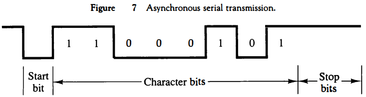
With this technique, each character consists of three parts: a start bit, the character bits, and stop bits. The convention is that the transmitter rests at the 1-state when no characters are transmitted. The first bit, called the start bit, is always a 0 and is used to indicate the beginning of a character.
The last bit called the stop bit is always a 1. An example of this format is shown in Fig. 7.
A transmitted character can be detected by the receiver from knowledge of the transmission rules:
1. When a character is not being sent, the line is kept in the 1-state.
2. The initiation of a character transmission is detected from the start bit,
which is always 0.
3. The character bits always follow the start bit.
4. After the last bit of the character is transmitted, a stop bit is detected
when the line returns to the 1-state for at least one bit time.
Using these rules, the receiver can detect the start bit when the line goes from
1 to 0.
A clock in the receiver examines the line at proper bit times. The receiver knows the transfer rate of the bits and the number of character bits to accept. After the character bits are transmitted, one or two stop bits are sent.
The stop bits are always in the 1-state and frame the end of the character to signify the idle or wait state.
At the end of the character the line is held at the 1-state for a period of at least one or two bit times so that both the transmitter and receiver can resynchronize.
The length of time that the line stays in this state depends on the amount of time required for the equipment to resynchronize. Some older electromechanical terminals use two stop bits, but newer terminals use one stop bit. The line remains in the 1-state until another character is transmitted.
The stop time ensures that a new character will not follow for one or two bit times.
As an illustration, consider the serial transmission of a terminal whose transfer rate is 10 characters per second. Each transmitted character consists
of a start bit, eight information bits, and two stop bits, for a total of 11 bits.
Ten characters per second means that each character takes 0.1 s for transfer. Since there are 11 bits to be transmitted, it follows that the bit time is 9.09 ms.
The baud rate is defined as the rate at which serial information is transmitted and is equivalent to the data transfer in bits per second. Ten characters per second with an 11-bit format has a transfer rate of 110 baud.
The terminal has a keyboard and a printer. Every time a key is depressed, the terminal sends 11 bits serially along a wire. To print a character in the printer, an 11-bit message must be received along another wire. The terminal interface consists of a transmitter and a receiver.
The transmitter accepts an 8-bit character from the computer and proceeds to send a serial 11-bit message into the printer line. The receiver accepts a serial 11-bit message from the keyboard line and forwards the 8-bit character code into the computer.
Integrated circuits are available which are specifically designed to provide the interface between computer and similar interactive terminals. Such a circuit is called an asynchronous communication interface or a universal asynchronous receivertransmitter (UART).