Modes of Transfer
Binary information received from an external device is usually stored in memory for later processing. Information transferred from the central computer into an external device originates in the memory unit.
The CPU merely executes the I/O instructions and may accept the data temporarily, but the ultimate source or destination is the memory unit.
Data transfer between the central computer and I/O devices may be handled in a variety of modes.
Some modes use the CPU as an intermediate path; others transfer the data directly to and from the memory unit.
Data transfer to and from peripherals may be handled in one of three possible modes:
1. Programmed I/O

2. Interrupt-initiated I/O

3. Direct memory access (DMA)
Programmed I/O operations are the result of I/O instructions written in the computer program.
Each data item transfer is initiated by an instruction in the program.
Usually, the transfer is to and from a CPU register and peripheral. Other instructions are needed to transfer the data to and from CPU and memory. Transferring data under program control requires constant monitoring of the peripheral by the CPU.
Once a data transfer is initiated, the CPU is required to monitor the interface to see when a transfer can again be made. It is up to the programmed instructions executed in the CPU to keep close tabs on everything that is taking place in the interface unit and the I/O device.
In the programmed I/O method, the CPU stays in a program loop until the I/O unit indicates that it is ready for data transfer. This is a time-consuming process since it keeps the processor busy needlessly.
It can be avoided by using an interrupt facility and special commands to inform the interface to issue an interrupt request signal when the data are available from the device. In the meantime the CPU can proceed to execute another program.
The interface meanwhile keeps monitoring the device. When the interface determines that the device is ready for data transfer, it generates an interrupt request to the computer. Upon detecting the external interrupt signal, the CPU momentarily stops the task it is processing, branches to a service program to process the I/O transfer, and then returns to the task it was originally performing.
Transfer of data under programmed I/O is between CPU and peripheral.
In direct memory access (DMA), the interface transfers data into and out of the memory unit through the memory bus. The CPU initiates the transfer by supplying the interface with the starting address and the number of words needed to be transferred and then proceeds to execute other tasks.
When the transfer is made, the DMA requests memory cycles through the memory bus.
When the request is granted by the memory controller, the DMA transfers the data directly into memory. The CPU merely delays its memory access operation to allow the direct memory I/O transfer.
Since peripheral speed is usually slower than processor speed, I/O-memory transfers are infrequent compared to processor access to memory.
Example of Programmed I/O
In the programmed I/O method, the I/O device does not have direct access to memory.
A transfer from an I/O device to memory requires the execution of several instructions by the CPU, including an input instruction to transfer the data from the device to the CPU and a store instruction to transfer the data from the CPU to memory.
Other instructions may be needed to verify that the data are available from the device and to count the numbers of words transferred.
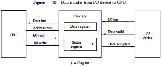
An example of data transfer from an I/O device through an interface into the CPU is shown in Fig. 10. The device transfers bytes of data one at a time as they are available.
When a byte of data is available, the device places it in the I/O bus and enables its data valid line.
The interface accepts the byte into its data register and enables the data accepted line.
The interface sets a bit in the status register that we will refer to as an F or "flag" bit. The device can now disable the data valid line, but it will not transfer another byte until the data accepted line is disabled by the interface.
This is according to the handshaking procedure established in Fig. 5.
A program is written for the computer to check the flag in the status register to determine if a byte has been placed in the data register by the I/O device.
This is done by reading the status register into a CPU register and checking the value of the flag bit.
If the flag is equal to 1, the CPU reads the data from the data register.
The flag bit is then cleared to 0 by either the CPU or the interface, depending on how the interface circuits are designed.
Once the flag is cleared, the interface disables the data accepted line and the device can then transfer the next data byte.
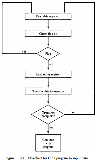
A flowchart of the program that must be written for the CPU is shown in Fig. 11. It is assumed that the device is sending a sequence of bytes that must be stored in memory.
The transfer of each byte requires three instructions:
1. Read the status register.
2. Check the status of the flag bit and branch to step 1 if not set or to step
3 if set.
3. Read the data register.
Each byte is read into a CPU register and then transferred to memory with a store instruction. A common I/O programming task is to transfer a block of words from an I/O device and store them in a memory buffer.
The programmed I/O method is particularly useful in small low-speed computers or in systems that are dedicated to monitor a device continuously.
The difference in information transfer rate between the CPU and the I/O device makes this type of transfer inefficient.
To see why this is inefficient, consider a typical computer that can execute the two instructions that read the status register and check the flag in 1 μS.
Assume that the input device transfers its data at an average rate of 100 bytes per second.
This is equivalent to one byte every 10,000 μS.
This means that the CPU will check the flag 10,000 times between each transfer.
The CPU is wasting time while checking the flag instead of doing some other useful processing task.
Interrupt-Initiated I/O
An alternative to the CPU constantly monitoring the flag is to let the interface inform the computer when it is ready to transfer data.
This mode of transfer uses the interrupt facility. While the CPU is running a program, it does not check the flag.
However, when the flag is set, the computer is momentarily interrupted from proceeding with the current program and is informed of the fact that the flag has been set.
The CPU deviates from what it is doing to take care of the input or output transfer.
After the transfer is completed, the computer returns to the previous program to continue what it was doing before the interrupt.
The CPU responds to the interrupt signal by storing the return address from the program counter into a memory stack and then control branches to a service routine that processes the required I/O transfer.
The way that the processor chooses the branch address of the service routine varies from one unit to another.
In principle, there are two methods for accomplishing this.
One is called vectoredinterrupt and the other, nonvectored interrupt. In a non vectored interrupt, the branch address is assigned to a fixed location in memory.
In a vectored interrupt, the source that interrupts supplies the branch information to the computer. This information is called the interrupt vector.
In some computers the interrupt vector is the first address of the I/O service routine.
In other computers the interrupt vector is an address that points to a location in memory where the beginning address of the I/O service routine is stored.
Priority Interrupt
Data transfer between the CPU and an I/O device is initiated by the CPU. However, the CPU cannot start the transfer unless the device is ready to communicate with the CPU.
The readiness of the device can be determined from an interrupt signal. The CPU responds to the interrupt request by storing the return address from PC into a memory stack and then the program branches to a service routine that processes the required transfer.
Some processors also push the current PSW (program status word) onto the stack and load a new PSW for the service routine.
In a typical application a number of I/O devices are attached to the computer, with each device being able to originate an interrupt request. The first task of the interrupt system is to identify the source of the interrupt.
There is also the possibility that several sources will request service simultaneously. In this case the system must also decide which device to service first.
A priority interrupt is a system that establishes a priority over the various sources to determine which condition is to be serviced first when two or more requests arrive simultaneously.
The system may also determine which conditions are permitted to interrupt the computer while another interrupt is being serviced.
Higher-priority interrupt levels are assigned to requests which, if delayed or interrupted, could have serious consequences.
Devices with high speed transfers such as magnetic disks are given high priority, and slow devices such as keyboards receive low priority.
When two devices interrupt the computer at the same time, the computer services the device, with the higher priority first.
Establishing the priority of simultaneous interrupts can be done by software or hardware.
A polling procedure is used to identify the highest-priority source by software means.
In this method there is one common branch address for all interrupts.
The program that takes care of interrupts begins at the branch address and polls the interrupt sources in sequence. The order in wJ;tich they are tested determines the priority of each interrupt.
The highest-priority source is tested first, and if its interrupt signal is on, control branches to a service routine for this source.
Otherwise, the next-lower-priority source is tested, and so on. Thus the initial service routine for all interrupts consists of a program that tests the interrupt sources in sequence and branches to one of many possible service routines.
The particular service routine reached belongs to the highest-priority device among all devices that interrupted the computer.
The disadvantage of the software method is that if there are many interrupts, the time required to poll them can exceed the time available to service the I/O device. In this situation a hardware priority-interrupt unit can be used to speed up the operation.
A hardware priority-interrupt unit functions as an overall manager in an interrupt system environment.
It accepts interrupt requests from many sources, determines which of the incoming requests has the highest priority, and issues an interrupt request to the computer based on this determination.
To speed up the operation, each interrupt source has its own interrupt vector to access its own service routine directly. Thus no polling is required because all the decisions are established by the hardware priority-interrupt unit.
The hardware priority function can be established by either a serial or a parallel connection of interrupt lines. The serial connection is also known as the daisychaining method.