Daisy-Chaining Priority
The daisy-chaining method of establishing priority consists of a serial connection of all devices that request an interrupt.
The device with the highest priority is placed in the first position, followed by lower-priority devices up to the device with the lowest priority, which is placed last in the chain.
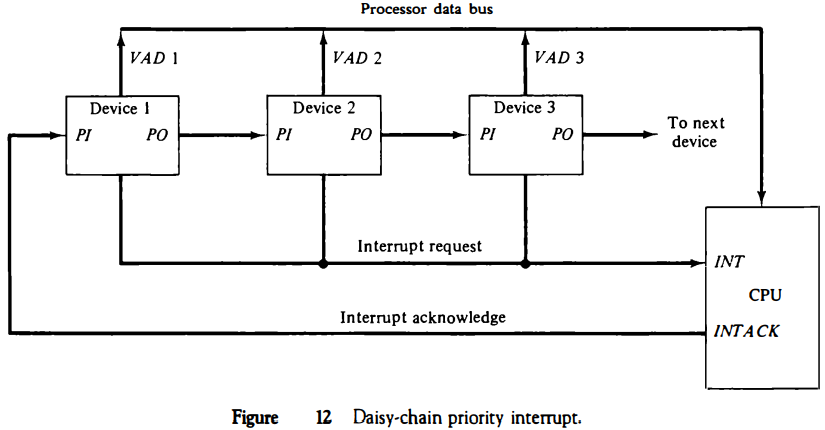
This method of connection between three devices and the CPU is shown in Fig. 12. The interrupt request line is common to all devices and forms a wired logic connection.
If any device has its interrupt signal in the low-level state, the interrupt line goes to the low-level state and enables the interrupt input in the CPU.
When no interrupts are pending, the interrupt line stays in the high-level state and no interrupts are recognized by the CPU.
This is equivalent to a negativelogic OR operation. The CPU responds to an interrupt request by enabling the interrupt acknowledge line. This signal is received by device 1 at its PI (priority in) input.
The acknowledge signal passes on to the next device through the PO (priority out) output only if device 1 is not requesting an interrupt.
If device 1 has a pending interrupt, it blocks the acknowledge signal from the next device by placing a 0 in the PO output.
It then proceeds to insert its own interrupt vector address (VAD) into the data bus for the CPU to use during the interrupt cycle.
A device with a 0 in its PI input generates a 0 in its PO output to inform the next-lower-priority device that the acknowledge signal has been blocked.
A device that is requesting an interrupt and has a 1 in its PI input will intercept the acknowledge signal by placing a 0 in its PO output.
If the device does not have pending interrupts, it transmits the acknowledge signal to the next device by placing a 1 in its PO output.
Thus the device with PI = 1 and PO = 0 is the one with the highest priority that is requesting an interrupt, and this device places its VAD on the data bus.
The daisy chain arrangement gives the highest priority to the device that receives the interrupt acknowledge signal from the CPU.
The farther the device is from the first position, the lower is its priority.
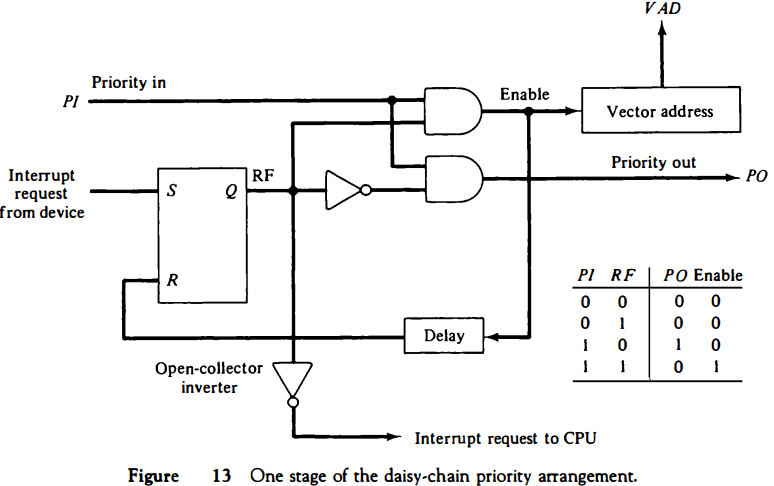
Figure 13 shows the internal logic that must be included within each device when connected in the daisy-chaining scheme. The device sets its RF flip-flop when it wants to interrupt the CPU.
The output of the RF flip-flop goes through an open-collector inverter, a circuit that provides the wired logic for the common interrupt line.
If PI = 0, both PO and the enable line to VAD are equal to 0, irrespective of the value of RF. If PI = 1 and RF = 0, then PO = 1 and the vector address is disabled.
This condition passes the acknowledge signal to the next device through PO.
The device is active when PI = 1 and RF = 1. This condition places a 0 in PO and enables the vector address for the data bus.
It is assumed that each device has its own distinct vector address. The RF flip-flop is reset after a sufficient delay to ensure that the CPU has received the vector address.
Parallel Priority Interrupt
The parallel priority interrupt method uses a register whose bits are set separately by the interrupt signal from each device.
Priority is established according to the position of the bits in the register.
In addition to the interrupt register, the circuit may include a mask register whose purpose is to control the status of each interrupt request.
The mask register can be programmed to disable lower-priority interrupts while a higher-priority device is being serviced.
It can also provide a facility that allows a high-priority device to interrupt the CPU while a lower-priority device is being serviced.
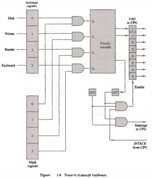
The priority logic for a system of four interrupt sources is shown in Fig. 14.
It consists of an interrupt register whose individual bits are set by external conditions and cleared by program instructions.
The magnetic disk, being a high-speed device, is given the highest priority. The printer has the next priority, followed by a character reader and a keyboard.
The mask register has the same number of bits as the interrupt register. By means of program instructions, it is possible to set or reset any bit in the mask register.
Each interrupt bit and its corresponding mask bit are applied to an AND gate to produce the four inputs to a priority encoder.
In this way an interrupt is recognized only if its corresponding mask bit is set to 1 by the program. The priority encoder generates two bits of the vector address, which is transferred to the CPU.
Another output from the encoder sets an interrupt status flip-flop lST when an interrupt that is not masked occurs. The interrupt enable flip-flop lEN can be set or cleared by the program to provide an overall control over the interrupt system.
The outputs of IST ANDed with IEN provide a common interrupt signal for the CPU.
The interrupt acknowledge INTACK signal from the CPU enables the bus buffers in the output register and a vector address VAD is placed into the data bus.
Direct Memory Access (DMA)
The transfer of data between a fast storage device such as magnetic disk and memory is often limited by the speed of the CPU.
Removing the CPU from the path and letting the peripheral device manage the memory buses directly
The data formats of peripheral devices differ from memory and CPU data formats. The IOP must structure data words from many different sources.
For example, it may be necessary to take four bytes from an input device and pack them into one 32-bit word before the transfer to memory.
Data are gathered in the IOP at the device rate and bit capacity while the CPU is executing its own program.
After the input data are assembled into a memory word, they are transferred from IOP directly into memory by "stealing" one memory cycle from the CPU.
Similarly, an output word transferred from memory to the lOP is directed from the IOP to the output device at the device rate and bit capacity.
The communication between the IOP and the devices attached to it is similar to the program control method of transfer. Communication with the memory is similar to the direct memory access method.
The way by which the CPU and IOP communicate depends on the level of sophistication included in the system.
In very-large-scale computers, each processor is independent of all others and any one processor can initiate an operation. In most computer systems, the CPU is the master while the IOP is a slave processor.
The CPU is assigned the task of initiating all operations, but 110 instructions are executed in the IOP.
CPU instructions provide operations to start an 110 transfer and also to test 110 status conditions needed for making decisions on various 110 activities.
The IOP, in turn, typically asks for CPU attention by means of an interrupt.
It also responds to CPU requests by placing a status word in a prescribed location in memory to be examined later by a CPU program.
When an 110 operation is desired, the CPU informs the IOP where to find the 110 program and then leaves the transfer details to the IOP.
Instructions that are read from memory by an IOP are sometimes called commands, to distinguish them from instructions that are read by the CPU. Otherwise, an instruction and a command have similar functions.
Commands are prepared by experienced programmers and are stored in memory. The command words constitute the program for the IOP.
The CPU informs the IOP where to find the commands in memory when it is time to execute the 110 program.
CPU-IOP Communication
The communication between CPU and IOP may take different forms, depending on the particular computer considered.
In most cases the memory unit acts as a message center where each processor leaves information for the other.
To appreciate the operation of a typical IOP, we will illustrate by a specific example the method by which the CPU and IOP communicate.
This is a simplified example that omits many operating details in order to provide an overview of basic concepts.
The sequence of operations may be carried out as shown in the flowchart of Fig. 20.
The CPU sends an instruction to test the IOP path.
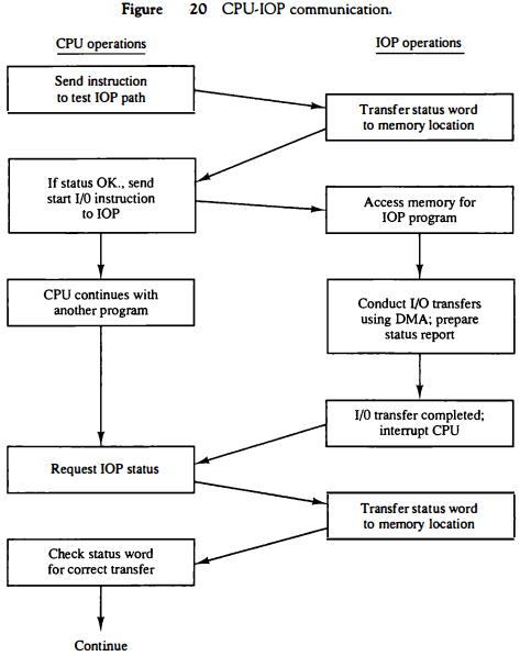
The IOP responds by inserting a status word in memory for the CPU to check.
The bits of the status word indicate the condition of the IOP and I/O device, such as IOP overload condition, device busy with another transfer, or device ready for I/O transfer.
The CPU refers to the status word in memory to decide what to do next. If all is in order, the CPU sends the instruction to start I/O transfer.
The memory address received with this instruction tells the IOP where to find its program.
The CPU can now continue with another program while the IOP is busy with the I/O program. Both programs refer to memory by means of DMA transfer.
When the IOP terminates the execution of its program, it sends an interrupt request to the CPU. The CPU responds to the interrupt by issuing an instruction to read the status from the IOP.
The IOP responds by placing the contents of its status report into a specified memory location. The status word indicates whether the transfer has been completed or if any errors occurred during the transfer.
From inspection of the bits in the status word, the CPU determines if the I/O operation was completed satisfactorily without errors.
The IOP takes care of all data transfers between several I/O units and the memory while the CPU is processing another program.
The IOP and CPU are competing for the use of memory, so the number of devices that can be in operation is limited by the access time of the memory.
It is not possible to saturate the memory by I/O devices in most systems, as the speed of most devices is much slower than the CPU.
However, some very fast units, such as magnetic disks, can use an appreciable number of the available memory cycles.
In that case, the speed of the CPU may deteriorate because it will often have to wait for the IOP to conduct memory transfers.