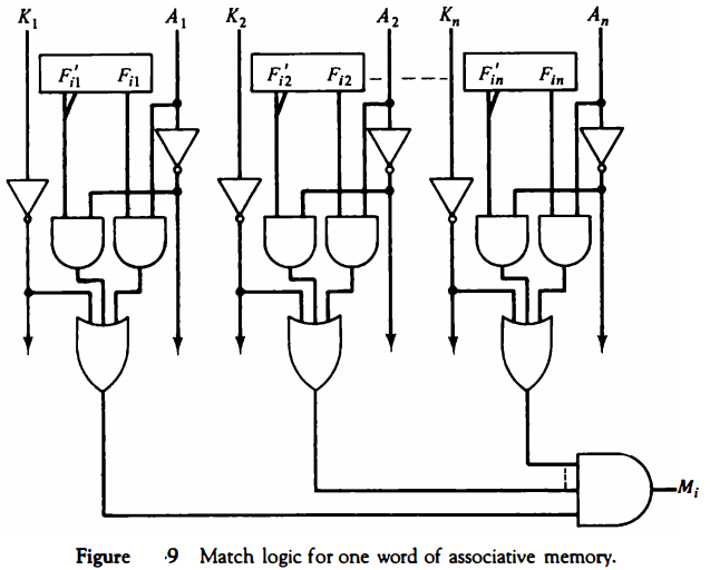
Match Logic
The match logic for each word can be derived from the comparison algorithm for two binary numbers.
First, we neglect the key bits and compare the argument in A with the bits stored in the cells of the words. Word i is equal to the argument in A if Aj = Fij for j = 1, 2, ... , n. Two bits are equal if they are both 1 or both 0.
The equality of two bits can be expressed logically by the Boolean function \( x_j = A_j F_{ij} + A'_jF'_{ij} \) where xj = 1 if the pair of bits in position j are equal; otherwise, xj = 0.
For a word i to be equal to the argument in A we must have all xj variables equal to 1.
This is the condition for setting the corresponding match bit Mi to 1. The Boolean function for this condition is \( M_i = x_1x_2x_3 ... x_n \) and constitutes the AND operation of all pairs of matched bits in a word.
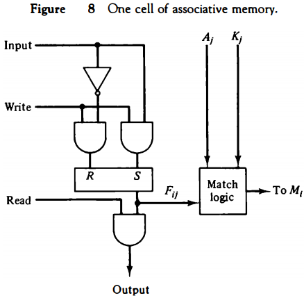
We now include the key bit Kj in the comparison logic. The requirement is that if Kj = 0, the corresponding bits of Aj and Fij need no comparison. Only when Kj = 1 must they be compared. This requirement is achieved by ORing each term with K'j thus:
When Kj = 1, we have K'j = 0 and xj + 0 = xj . When Kj = 0, then K'j = 1 and xj + 1 = 1. A term (xj + K'j) will be in the 1 state if its pair of bits is not compared.
This is necessary because each term is ANDed with all other terms so that an output of 1 will have no effect. The comparison of the bits has an effect only when Kj = 1.
The match logic for word i in an associative memory can now be expressed by the following Boolean function:
Each term in the expression will be equal to 1 if its corresponding Kj = 0. If Kj = 1, the term will be either 0 or 1 depending on the value of Xj. A match will occur and Mj will be equal to 1 if all terms are equal to 1.
If we substitute the original definition of xj, the Boolean function above can be expressed as follows:
where ∏ is a product symbol designating the AND operation of all n terms. We need m such functions, one for each word i = 1, 2, 3, ... , m.
The circuit for matching one word is shown in Fig. 9. Each cell requires two AND gates and one OR gate. The inverters for Aj and Kj are needed once for each column and are used for all bits in the column.
The output of all OR gates in the cells of the same word go to the input of a common AND gate to generate the match signal for Mi. Mi will be logic 1 if a match occurs and 0 if no match occurs.
Note that if the key register contains all 0' s, output Mj will be a 1 irrespective of the value of A or the word. This occurrence must be avoided during normal operation.
Read Operation
If more than one word in memory matches the unmasked argument field, all the matched words will have 1's in the corresponding bit position of the match register.
It is then necessary to scan the bits of the match register one at a time. The matched words are read in sequence by applying a read signal to each word line whose corresponding Mi bit is a 1.
In most applications, the associative memory stores a table with no two identical items'under a given key.
In this case, only one word may match the unmasked argument field. By connecting output Mi directly to the read line in the same word position (instead of the M register), the content of the matched word will be presented automatically at the output lines and no special read command signal is needed.
Furthermore, if we exclude words having a zero content, an all-zero output will indicate that no match occurred and that the searched item is not available in memory
Write Operation
An associative memory must have a write capability for storing the information to be searched.
Writing in an associative memory can take different forms, depending on the application.
If the entire memory is loaded with new information at once prior to a search operation then the writing can be done by addressing each location in sequence.
This will make the device a randomaccess memory for writing and a content addressable memory for reading. The advantage here is that the address for input can be decoded as in a randomaccess memory.
Thus instead of having m address lines, one for each word in memory, the number of address lines can be reduced by the decoder to d lines, where m = 2d.
If unwanted words have to be deleted and new words inserted one at a time, there is a need for a special register to distinguish between active and inactive words.
This register, sometimes called a tag register, would have as many bits as there are words in the memory.
For every active word stored in memory, the corresponding bit in the tag register is set to 1. A word is deleted from memory by clearing its tag bit to 0. Words are stored in memory by scanning the tag register until the first 0 bit is encountered.
This gives the first available inactive word and a position for writing a new word. After the new word is stored in memory it is made active by setting its tag bit to 1. An unwanted word when deleted from memory can be cleared to all 0' s if this value is used to specify an empty location.
Moreover, the words that have a tag bit of 0 must be masked (together with the Kj bits) with the argument word so that only active words are compared.
Cache Memory
Analysis of a large number of typical programs has shown that the references to memory at any given interval of time tend to be confined within a few localized areas in memory.
This phenomenon is known as the property of locality of reference locality of reference.
The reason for this property may be understood considering that a typical computer program flows in a straight-line fashion with program loops and subroutine calls encountered frequently.
When a program loop is executed, the CPU repeatedly refers to the set of instructions in memory that constitute the loop. Every time a given subroutine is called, its set of instructions are fetched from memory.
Thus loops and subroutines tend to localize the references to memory for fetching instructions. To a lesser degree, memory references to data also tend to be localized.
Table-lookup procedures repeatedly refer to that portion in memory where the table is stored. Iterative procedures refer to common memory locations and array of numbers are confined within a local portion of memory.
The result of all these observations is the locality of reference property, which states that over a short interval of time, the addresses generated by a typical program refer to a few localized areas of memory repeatedly, while the remainder of memory is accessed relatively infrequently.
If the active portions of the program and data are placed in a fast small memory, the average memory access time can be reduced, thus reducing the total execution time of the program.
Such a fast small memory is referred to as a cache memory. It is placed between the CPU and main memory as illustrated in Fig. 1 .
The cache memory access time is less than the access time of main memory by a factor of 5 to 10. The cache is the fastest component in the memory hierarchy and approaches the speed of CPU components.
The fundamental idea of cache organization is that by keeping the most frequently accessed instructions and data in the fast cache memory, the aver-age memory access time will approach the access time of the cache.
Although the cache is only a small fraction of the size of main memory, a large fraction of memory requests will be found in the fast cache memory because of the locality of reference property of programs.
The basic operation of the cache is as follows. When the CPU needs to access memory, the cache is examined. If the word is found in the cache, it is read from the fast memory.
If the word addressed by the CPU is not found in the cache, the main memory is accessed to read the word. A block of words containing the one just accessed is then transferred from main memory to cache memory. The block size may vary from one word (the one just accessed) to about 16 words adjacent to the one just accessed. In this manner, some data are transferred to cache so that future references to memory find the required words in the fast cache memory.
The performance of cache memory is frequently measured in terms of a quantity called hit ratio . When the CPU refers to memory and finds the word in cache, it is said to produce a hit. If the word is not found in cache, it is in main memory and it counts as a miss.
The ratio of the number of hits divided by the total CPU references to memory (hits plus misses) is the hit ratio.
The hit ratio is best measured experimentally by running representative programs in the computer and measuring the number of hits and misses during a given interval of time.
Hit ratios of 0.9 and higher have been reported. This high ratio verifies the validity of the locality of reference property.
The average memory access time of a computer system can be improved considerably by use of a cache. If the hit ratio is high enough so that most of the time the CPU accesses the cache instead of main memory, the average access time is closer to the access time of the fast cache memory.
For example, a computer with cache access time of 100 ns, a main memory access time of 1000 ns, and a hit ratio of 0.9 produces an average access time of 200 ns. This is a considerable improvement over a similar computer without a cache memory, whose access time is 1000 ns.
The basic characteristic of cache memory is its fast access time. Therefore, very little or no time must be wasted when searching for words in the cache. The transformation of data from main memory to cache memory is referred to as a mapping process.
  Three types of mapping procedures are of practical
interest when considering the organization of cache memory:
1. Associative mapping
2. Direct mapping
3. Set-associative mapping
To help in the discussion of these three mapping procedures we wi)l use a specific example of a memory organization as shown in Fig. 10. The main memory can store 32K words of 12 bits each.
The cache is capable of storing 512 of these words at any given time. For every word stored in cache, there is a duplicate copy in main memory.
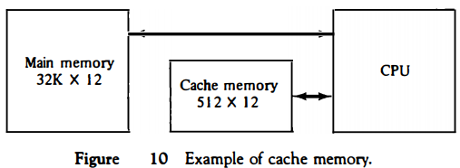
The CPU communicates with both memories. It first sends a 15-bit address to cache. If there is a hit, the CPU accepts the 12-bit data from cache. If there is a miss, the CPU reads the word from main memory and the word is then transferred to cache.
Associative Mapping
The fastest and most flexible cache organization uses an associative memory. This organization is illustrated in Fig. 11.
The associative memory stores both the address and content (data) of the memory word.
This permits any location in cache to store any word from main memory.
The diagram shows three words presently stored in the cache.
The address value of 15 bits is shown as a five-digit octal number and its corresponding 12-bit word is shown as a four-digit octal number.
A CPU address of 15 bits is placed in the argument register and the associative memory is searched for a matching address.
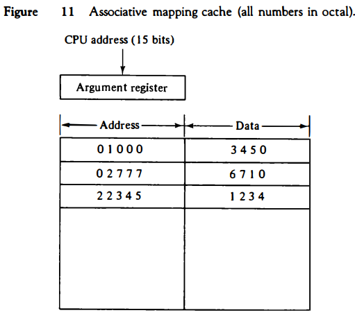
If the address is found, the corresponding 12-bit data is read and sent to the CPU.
If no match occurs, the main memory is accessed for the word. The address--data pair is then transferred to the associative cache memory.
If the cache is full, an address--data pair must be displaced to make room for a pair that is needed and not presently in the cache.
The decision as to what pair is replaced is determined from the replacement algorithm that the designer chooses for the cache.
A simple procedure is to replace cells of the cache in round-robin order whenever a new word is requested from main memory.
This constitutes a first-in first-out (FIFO) replacement policy.
Direct Mapping
Associative memories are expensive compared to random-access memories because of the added logic associated with each cell.
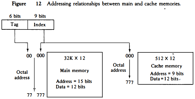
The possibility of using a random-access memory for the cache is investigated in Fig. 12.
The CPU address of 15 bits is divided into two fields. The nine least significant bits constitute the index field and the remaining six bits form the tag field.
The figure shows that main memory needs an address that includes both the tag and the index bits.
The number of bits in the index field is equal to the number of address bits required to access the cache memory.
In the general case, there are 2k words in cache memory and 2n words in main memory.
The n-bit memory address is divided into two fields: k bits for the index field and n - k bits for the tag field.
The direct mapping cache organization uses the n-bit address to access the main memory and the k-bit index to access the cache.
The internal organization of the words in the cache memory is as shown in Fig. 13(b).
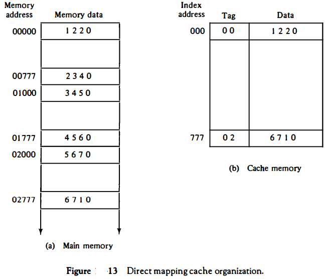
Each word in cache consists of the data word and its associated tag.
When a new word is first brought into the cache, the tag bits are stored alongside the data bits.
When the CPU generates a memory request, the index field is used for the address to access the cache.
The tag field of the CPU address is compared with the tag in the word read from the cache.
If the two tags match, there is a hit and the desired data word is in cache.
If there is no match, there is a miss and the required word is read from main memory. It is then stored in the cache together with the new tag, replacing the previous value.
The disadvantage of direct mapping is that the hit ratio can drop considerably if two or more words whose addresses have the same index but differenttags are accessed repeatedly.
However, this possibility is minimized by the fact that such words are relatively far apart in the address range (multiples of 512 locations in this example.)
To see how the direct-mapping organization operates, consider the numerical example shown in Fig. 13. The word at address zero is presently stored in the cache (index = 000, tag = 00, data = 1220).
Suppose that the CPU now wants to access the word at address 02000. The index address is 000, so it is used to access the cache. The two tag_s are then compared.
The cache tag is 00 but the address tag is 02, which does not produce a match. Therefore, the main memory is accessed and the data word 5670 is transferred to the CPU.
The cache word at index address 000 is then replaced with a tag of 02 and data of 5670.
The direct-mapping example just described uses a block size of one word. The same organization but using a block size of B words is shown in Fig. 14.
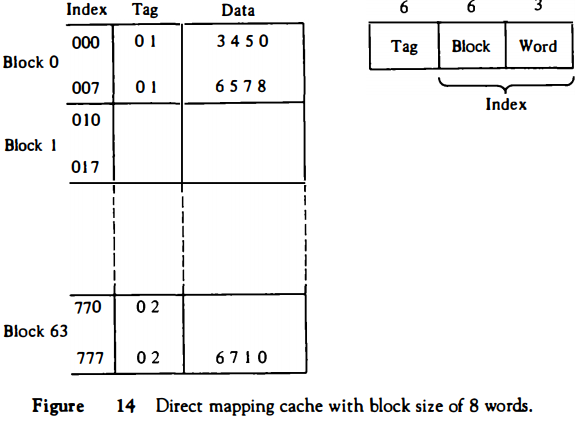
The index field is now divided into two parts: the block field and the word field.
In a 512-word cache there are 64 blocks of 8 words each, since 64 x 8 = 512.
The block number is specified with a 6-bit field and the word within the block is specified with a 3-bit field.
The tag field stored within the cache is common to all eight words of the same block.
Every time a miss occurs, an entire block of eight words must be transferred from main memory to cache memory.
Although this takes extra time, the hit ratio will most likely improve with a larger block size because of the sequential nature of computer programs.
Set-Associative Mapping
It was mentioned previously that the disadvantage of direct mapping is that two words with the same index in their address but with different tag values cannot reside in cache memory at the same time.
A third type of cache organization, called set-associative mapping, is an improvement over the directmapping organization in that each word of cache can store two or more words of memory under the same index address.
Each data word is stored together with its tag and the number of tag-data items in one word of cache is said to form a set.
An example of a set-associative cache organization for a set size of two is shown in Fig. 15.
Each index address refers to two data words and their associated tags. Each tag requires six bits and each data word has 12 bits, so the word length is 2(6 + 12) = 36 bits. An index address of nine bits can accommodate 512 words. Thus the size of cache memory is 512 x 36.
It can accommodate 1024 words of main memory since each word of cache contains two data words.
In general, a set-associative cache of set size k will accommodate k words of main memory in each word of cache.
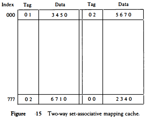
The octalnumbers listed in Fig. 15 are with reference to the main memory contents illustrated in Fig. 13(a).
The words stored at addresses 01000 and 02000 of main memory are stored in cache memory at index address 000.
Similarly, the words at addresses 02777 and 00777 are stored in cache at index address 777.
When the CPU generates a memory request, the index value of the address is used to access the cache. The tag field of the CPU address is then compared with both tags in the cache to determine if a match occurs.
The comparison logic is done by an associative search of the tags in the set similar to an associative memory search: thus the name "set-associative."
The hit ratio will improve as the set size increases because more words with the same index but different tags can reside in cache.
However, an increase in the set size increases the number of bits in words of cache and requires more complex comparison logic.
When a miss occurs in a set-associative cache and the set is full, it is necessary to replace one of the tag-data items with a new value.
The most common replacement algorithms used are: random replacement, first-in, firstout (FIFO), and least recently used (LRU).
With the random replacement policy the control chooses one tag-data item for replacement at random. The FIFO procedure selects for replacement the item that has been in the set the longest.
The LRU algorithm selects for replacement the item that has been least recently used by the CPU.
Both FIFO and LRU can be implemented by adding a few extra bits in each word of cache.
Writing into Cache
An important aspect of cache organization is concerned with memory write requests. When the CPU finds a word in cache during a read operation, the main memory is not involved in the transfer.
However, if the operation is a write, there are two ways that the system can proceed.
The simplest and most commonly used procedure is to update main memory with every memory write operation, with cache memory being updated in parallel if it contains the word at the specified address.
This is called the write-through method.
This method has the advantage that main memory always contains the same data as the cache.
This characteristic is important in systems with direct memory access transfers.
It ensures that the data residing in main memory are valid at all times so that an 110 device communicating through DMA would receive the most recent updated data.
The second procedure is called the write-back method. In this method only the cache location is updated during a write operation.
The location is then marked by a flag so that later when the word is removed from the cache it is copied into main memory.
The reason for the write-back method is that during the time a word resides in the cache, it may be updated several times; however, as long as the word remains in the cache, it does not matter whether the copy in main memory is out of date, since requests from the word are filled from the cache.
It is only when the word is displaced from the cache that an accurate copy need be rewritten into main memory.
Analytical results indicate that the number of memory writes in a typical program ranges between 10 and 30 percent of the total references to memory.
Cache Initialization
One more aspect of cache organization that must be taken into consideration is the problem of initialization.
The cache is initialized when power is applied to the computer or when the main memory is loaded with a complete set of programs from auxiliary memory.
After initialization the cache is considered to be empty, but in effect it contains some nonvalid data.
It is customary to include with each word in cache a valid bit to indicate whether or not the word contains valid data.
The cache is initialized by clearing all the valid bits to 0.
The valid bit of a particular cache word is set to 1 the first time this word is loaded from main memory and stays set unless the cache has to be initialized again.
The introduction of the valid bit means that a word in cache is not replaced by another word unless the valid bit is set to 1 and a mismatch of tags occurs.
If the valid bit happens to be 0, the new word automatically replaces the invalid data.
Thus the initialization condition has the effect of forcing misses from the cache until it fills with valid data.
Virtual Memory
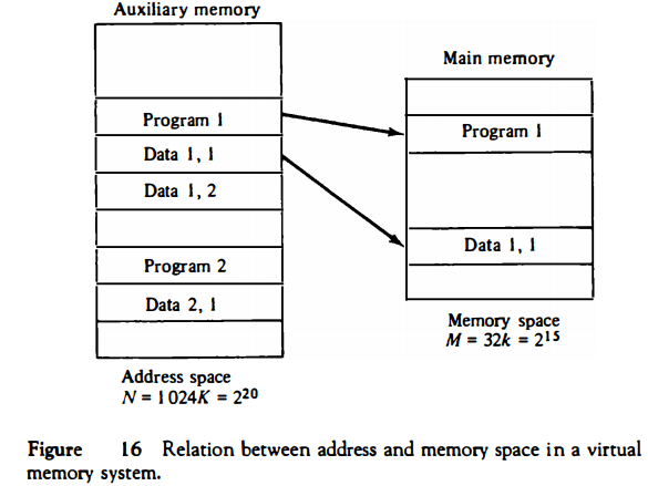
In a memory hierarchy system, programs and data are first stored in auxiliary memory. Portions of a program or data are brought into main memory as they are needed by the CPU.
Virtual memory is a concept used in some large computer systems that permit the user to construct programs as though a large memory space were available, equal to the totality of auxiliary memory.
Each address that is referenced by the CPU goes through an address mapping from the so-called virtual address to a physical address in main memory.
Virtual memory is used to give programmers the illusion that they have a very large memory at their disposal, even though the computer actually has a relatively small main memory.
A virtual memory system provides a mechanism for translating program-generated addresses into correct main memory locations. This is done dynamically, while programs are being executed in the CPU.
The translation or mapping is handled automatically by the hardware by means of a mapping table.
Address Space and Memory Space
An address used by a programmer will be called a virtual address, and the set of such addresses the address space.
An address in main memory is called a location or physical address.
The set of such locations is called the memory space.
Thus the address space is the set of addresses generated by programs as they reference instructions and data; the memory space consists of the actual main memory locations directly addressable for processing.
In most computers the address and memory spaces are identical. The address space is allowed to be larger than the memory space in computers with virtual memory.
As an illustration, consider a computer with a main-memory capacity of 32K words (K = 1024). Fifteen bits are needed to specify a physical address in 鐚� memory since 32K = 215. Suppose that the computer has available auxiliary memory for storing 220 = 1024K words.
Thus auxiliary memory has a capacity for storing information equivalent to the capacity of 32 main memories. Denoting the address space by N and the memory space by M, we then have for this example N = 1024K and M = 32K.
In a multiprogram computer system, programs and data are transferred to and from auxiliary memory and main memory based on demands imposed by the CPU.
Suppose that program 1 is currently being executed in the CPU. Program 1 and a portion of its associated data are moved from auxiliary memory into main memory as shown in Fig. 16.
Portions of programs and data need not be in contiguous locations in memory since information is being moved in and out, and empty spaces may be available in scattered locations in memory.
In a virtual memory system, programmers are told that they have the total address space at their disposal.
Moreover, the address field of the instruction code has a sufficient number of bits to specify all virtual addresses.
In our example, the address field of an instruction code will consist of 20 bits but physical memory addresses must be specified with only 15 bits.
Thus CPU will reference instructions and data with a 20-bit address, but the information at this address must be taken from physical memory because access to auxiliary storage for individual words will be prohibitively long.
(Remember that for efficient transfers, auxiliary storage moves an entire record to the main memory.)
A table is then needed, as shown in Fig. 17, to map a virtual address of 20 bits to a physical address of 15 bits. The mapping is a dynamic operation, which means that every address is translated inunediately as a word is referenced by CPU.
The mapping table may be stored in a separate memory as shown in Fig. 17 or in main memory. In the first case, an additional memory unit is required as well as one extra memory access time.
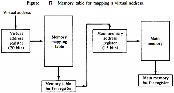
In the second case, the tab takes space from main memory and two accesses to memory are required with the program running at half speed.
Address Mapping Using Pages
The table implementation of the address mapping is simplified if the information in the address space and the memory space are each divided into groups of fixed size.
The physical memory is broken down into groups of equal size called blocks, which may range from 64 to 4096 words each.
The term page refers to groups of address space of the same size. For example, if a page or block consists of 1K words, then, using the previous example, address space is divided into 1024 pages and main memory is divided into 32 blocks.
Although both a page and a block are split into groups of 1K words, a page refers to the organization of address space, while a block refers to the organization of memory space.
The programs are also considered to be split into pages. Portions of programs are moved from auxiliary memory to main memory in records equal to the size of a page. The term "page frame" is sometimes used to denote a block.
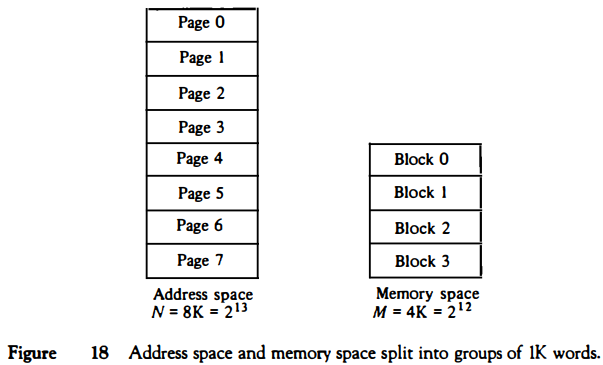
Consider a computer with an address space of 8K and a memory space of 4K.
If we split each into groups of 1K words we obtain eight pages and four blocks as shown in Fig. 18. At any given time, up to four pages of address space may reside in main memory in any one of the four blocks.
The mapping from address space to memory space is facilitated if each virtual address is considered to be represented by two numbers: a page number address and a line within the page.
In a computer with 2p words per page, p bits are used to specify a line address and the remaining high-order bits of the virtual address specify the page number. In the example of Fig. 18, a virtual address has 13 bits.
Since each page consists of 210 = 1024 words, the highorder three bits of a virtual address will specify one of the eight pages and the low-order 10 bits give the line address within the page. Note that the line address in address space and memory space is the same; the only mapping required is from a page number to a block number.
The organization of the memory mapping table in a paged system is shown in Fig. 19.
The memory-page table consists of eight words, one for each page. The address in the page table denotes the page number and the content of the word gives the block number where that page is stored in main memory.
The table shows that pages 1, 2, 5, and 6 are now available in main memory in blocks 3, 0, 1, and 2, respectively.
A presence bit in each location indicates whether the page has been transferred from auxiliary memory into main memory. A 0 in the presence bit indicates that this page is not available in main memory.
The CPU references a word in memory with a virtual address of 13 bits. The three high-order bits of the virtual address specify a page number and also an address for the memory-page table.
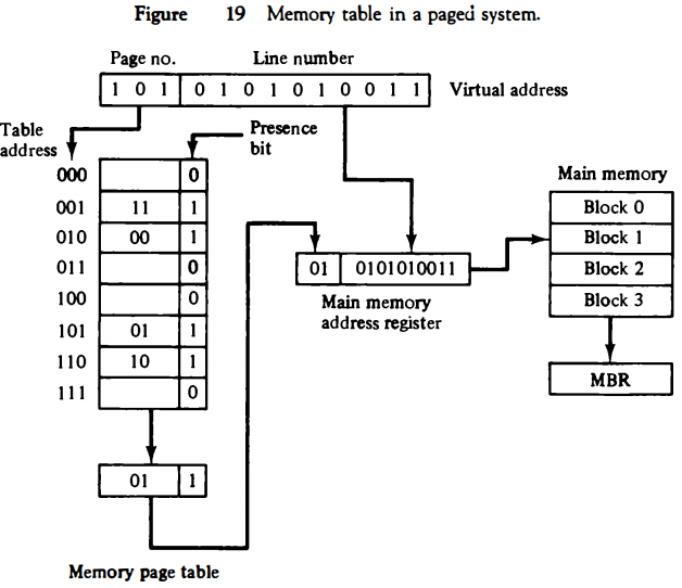
The content of the word in the memory page table at the page number address is read out into the memory table buffer register.
If the presence bit is a 1, the block number thus read is transferred to the two high-order bits of the main memory address register.
The line number from the virtual address is transferred into the 10 low-order bits of the memory address register. A read signal to main memor
transfers the content of the word to the main memory buffer register ready to be used by the CPU.
If the presence bit in the word read from the page table is 0, it signifies that the content of the word referenced by the virtual address does not reside in main memory.
A call to the operating system is then generated to fetch the required page from auxiliary memory and place it into main memory before resuming computation.
Associative Memory Page Table
A random-access memory page table is inefficient with respect to storage utilization.
In the example of Fig. 19 we observe that eight words of memory are needed, one for each page, but at least four words will always be marked empty because main memory cannot accommodate more than four blocks.
In general, a system with n pages and m blocks would require a memory-page table of n locations of which up to m blocks will be marked with block numbers and all others will be empty.
As a second numerical example, consider an address space of 1024K words and memory space of 32K words.
If each page or block contains 1K words, the number of pages is 1024 and the number of blocks 32. The capacity of the memory-page table must be 1024 words and only 32 locations may have a presence bit equal to 1.
At any given time, at least 992 locations will be empty and not in use.
A more efficient way to organize the page table would be to construct it with a number of words equal to the number of blocks in main memory.
In this way the size of the memory is reduced and each location is fully utilized. This method can be implemented by means of an associative memory with each word in memory containing a page number together with its corresponding block number.
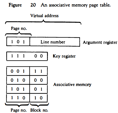
The page field in each word is compared with the page number in the virtual address.
If a match occurs, the word is read from memory and its corresponding block number is extracted. Consider again the case of eight pages and four blocks as in the example of Fig. 19.
We replace the random access memory-page table with an associative memory of four words as shown in Fig. 20. Each entry in the associative memory array consists of two fields. The first three bits specify a field for storing the page number. The last two bits constitute a field for storing the block number.
The virtual address is placed in the argument register. The page number bits in the argument register are compared with all page numbers in the page field of the associative memory.
If the page number is found, the 5-bit word is read out from memory.
The corresponding block number, being in the same word, is transferred to the main memory address register. If no match occurs, a call to the operating system is generated to bring the required page from auxiliary memory.