Page Replacement
A virtual memory system is a combination of hardware and software techniques. The memory management software system handles all the software operations for the efficient utilization of memory space.
It must decide (1) which page in main memory ought to be removed to make room for a new page, (2) when a new page is to be transferred from auxiliary memory to main memory, and (3) where the page is to be placed in main memory.
The hardware mapping mechanism and the memory management software together constitute the architecture of a virtual memory.
When a program starts execution, one or more pages are transferred into main memory and the page table is set to indicate their position.
The program is executed from main memory until it attempts to reference a page that is still in auxiliary memory.
This condition is called page fault. When page fault occurs, the execution of the present program is suspended until the required page is brought into main memory. Since loading a page from auxiliary memory to main memory is basically an I/O operation, the operating system assigns this task to the VO processor.
In the meantime, control is transferred to the next program in memory that is waiting to be processed in the CPU. Later, when the memory block has been assigned and the transfer completed, the original program can resume its operation.
When a page fault occurs in a virtual memory system, it signifies that the page referenced by the CPU is not in main memory.
A new page is then transferred from auxiliary memory to main memory. If main memory is full, it would be necessary to remove a page from a memory block to make room for the new page. The policy for choosing pages to remove is determined from the replacement algorithm that is used.
The goal of a replacement policy is to try to remove the page least likely to be referenced in the immediate future. Two of the most common replacement algorithms used are the first-in, first-out (FIFO) and the least recently used (LRU).
The FIFO algorithm selects for replacement the page that has been in memory the longest time. Each time a page is loaded into memory, its identification number is pushed into a FIFO stack. FIFO will be full whenever memory has no more empty blocks.
When a new page must be loaded, the page least recently brought in is removed. The page to be removed is easily determined because its identification number is at the top of the FIFO stack. The FIFO replacement policy has the advantage of being easy to implement.
It has the disadvantage that under certain circumstances pages are removed and loaded from memory too frequently.
LRU The LRU policy is more difficult to implement but has been more attractive on the assumption that the least recently used page is a better candidate for removal than the least recently loaded page as in FIFO.
The LRU algorithm can be implemented by associating a counter with every page that is in main memory. When a page is referenced, its associated counter is set to zero.
At fixed intervals of time, the counters associated with all pages presently in memory are incremented by 1. The least recently used page is the page with the highest count.
The counters are often called aging registers, as their count indicates their age, that is, how long ago their associated pages have been referenced.
Memory Management Hardware
In a multiprogramming environment where many programs reside in memory it becomes necessary to move programs and data around the memory, to vary the amount of memory in use by a given program, and to prevent a program from changing other programs.
The demands on computer memory brought about by multiprogramming have created the need for a memory management system. A memory management system is a collection of hardware and software procedures for managing the various programs residing in memory.
The memory management software is part of an overall operating system available in many computers. Here we are concerned with the hardware unit associated with the memory management system.
The basic components of a memory management unit are:

1. A facility for dynamic storage relocation that maps logical memory
references into physical memory addresses

2. A provision for sharing common programs stored in memory by different users

3. Protection of information against unauthorized access between users
and preventing users from changing operating system functions
The dynamic storage relocation hardware is a mapping process similar to the paging system. The fixed page size used in the virtual memory system causes certain difficulties with respect to program size and the logical structure of programs.
It is more convenient to divide programs and data into logical parts called segments. A segment is a set of logically related instructions or data elements associated with a given name.
Segments may be generated by the programmer or by the operating system.
Examples of segments are a subroutine, an array of data, a table of symbols, or a user's program.
The sharing of common programs is an integral part of a multiprogramming system. For example, several users wishing to compile their Fortran programs should be able to share a single copy of the compiler rather than each user having a separate copy in memory.
Other system programs residing in memory are also shared by all users in a multiprogramming system without having to produce multiple copies.
The third issue in multiprogramming is protecting one program from unwanted interaction with another.
An example of unwanted interaction is one user's unauthorized copying of another user's program. Another aspect of protection is concerned with preventing the occasional user from performing operating system functions and thereby interrupting the orderly sequence of operations in a computer installation.
The secrecy of certain programs must be kept from unauthorized personnel to prevent abuses in the confidential activities of an organization.
The address generated by a segmented program is called a logical address. This is similar to a virtual address except that logical address space is associated with variable-length segments rather than fixed-length pages.
The logical address may be larger than the physical memory address as in virtual memory, but it may also be equal, and sometimes even smaller than the length of the physical memory address.
In addition to relocation information, each segment has protection information associated with it. Shared programs are placed in a unique segment in each user's logical address space so that a single physical copy can be shared.
The function of the memory management unit is to map logical addresses into physical addresses similar to the virtual memory mapping concept.
Segmented-Page Mapping
It was already mentioned that the property of logical space is that it uses variable-length segments.
The length of each segment is allowed to grow and contract according to the needs of the program being executed.
One way of specifying the length of a segment is by associating with it a number of equal-size pages. To see how this is done, consider the logical address shown in Fig. 21 .
The logical address is partitioned into three fields. The segment field specifies a segment number. The page field specifies the page within the segment and the word field gives the specific word within the page. A page field of k bits can specify up to 2k pages.
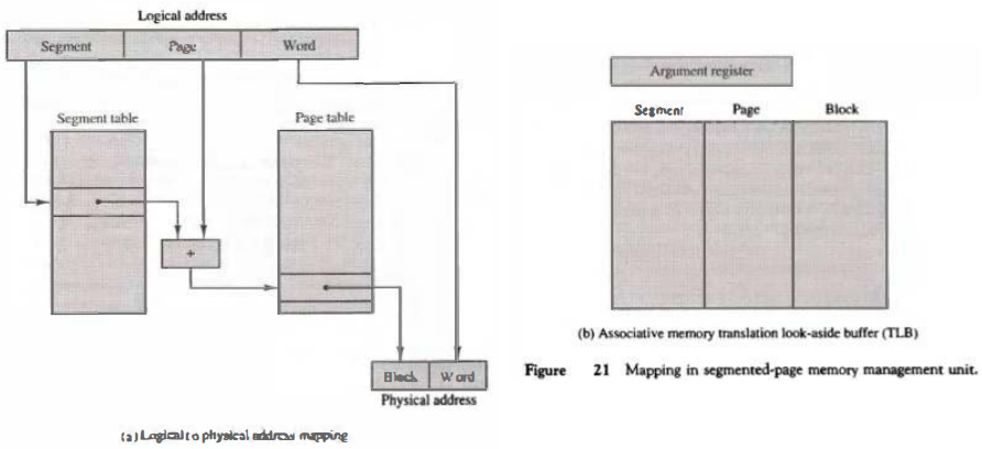
A segment number may be associated with just one page or with as many as 2k-pages. Thus the length of a segment would vary according to the number of pages that are assigned to it.
The mapping of the logical address into a physical address is done by means of two tables, as shown in Fig. 2l(a) The segment number of the logical address specifies the address for the segment table.
The entry in the segment table is a pointer address for a page table base. The page table base is added to the page number given in the logical address.
The sum produces a pointer address to an entry in the page table. The value found in the page table provides the block number in physical memory.
The concatenation of the block field with the word field produces the final physical mapped address. The two mapping tables may be stored in two separate small memories or in main memory.
In either case, a memory reference from the CPU will require three accesses to memory: one from the segment table, one from the page table, and the third from main memory.
This would slow the system significantly when compared to a conventional system that requires only one reference to memory.
To avoid this speed penalty, a fast associative memory is used to hold the most recently referenced table entries.
(This type of memory is sometimes called a translation lookaside buffer, abbreviated TLB.) The first time a given block is referenced, its value together with the corresponding segment and page numbers are entered into the associative memory as shown in Fig. 21(b).
Thus the mapping process is first attempted by associative search with the given segment and page numbers.
If it succeeds, the mapping delay is only that of the associative memory. If no match occurs, the slower table mapping of Fig. 21(a) is used and the result transformed into the associative memory for future reference.
Numerical Example
A numerical example may clarify the operation of the memory management unit. Consider the 20-bit logical address specified in Fig. 22(a). The 4-bit segment number specifies one of 16 possible segments.
The 8-bit page number can specify up to 256 pages, and the 8-bit word field implies a page size of 256 words.
This configuration allows each segment to have any number of pages up to 256. The smallest possible segment will have one page or 256 words. The largest possible segment will have 256 pages, for a total of 256 x 256 = 64K words.
The physical memory shown in Fig. 22(b) consists of 220 words of 32 bits each. The 20-bit address is divided into two fields: a 12-bit block number and an 8-bit word number.
Thus, physical memory is divided into 4096 blocks of 256 words each. A page in a logical address has a corresponding block in physical memory.
Note that both the logical and physical address have 20 bits. In the absence of a memory management unit, the 20-bit address from the CPU can be used to access physical memory directly.
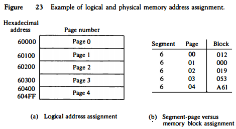
Consider a program loadedinto memory that requires five pages. The operating system may assign to this program segment 6 and pages 0 through 4, as shown in Fig. 23(a). The total logical address range for the program is from hexadecimal 60000 to 604FF.
When the program is loaded into physical memory, it is distributed among five blocks in physical memory where the operating system finds empty spaces. The correspondence between each memory block and logical page number is then entered in a table as shown in
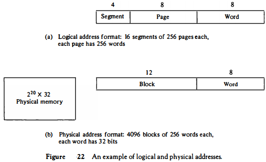
Fig. 23(b). The information from this table is entered in the segment and page tables as shown in Fig. 24(a). Now consider the specific logical address given in Fig. 24.
The 20-bit address is listed as a five-digit hexadecimal number.
It refers to word number 7E of page 2 in segment 6. The base of segment 6 in the page table is at address 35. Segment 6 has associated with it five pages, as shown in the page table at addresses 35 through 39.
Page 2 of segment 6 is at address 35 + 2 = 37. The physical memory block is found in the page table to be 019. Word 7E in block 19 gives the 20-bit physical address 0197E. Note that page 0 of segment 6 maps into block 12 and page 1 maps into block 0.
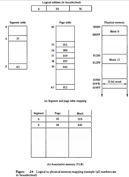
The associative memory in Fig. 24(b) shows that pages 2 and 4 of segment 6 have been referenced previously and therefore their corresponding block numbers are stored in the associative memory.
From this example it should be evident that the memory management system can assign any number of pages to each segment.
Each logical page can be mapped into any block in physical memory. Pages can move to different blocks in memory depending on memory space requirements.
The only updating required is the change of the block number in the page table. Segments can grow or shrink independently without affecting each other.
Different segments can use the same block of memory if it is required to share a program by many users.
For example, block number 12 in physical memory can be assigned a second logical address FOOOO through FOOFF. This specifies segment number 15 and page 0, which maps to block 12 as shown in Fig. 24(a).
Memory Protection
Memory protection can be assigned to the physical address or the logical address.
The protection of memory through the physical address can be done by assigning to each block in memory a number of protection bits that indicate the type of access allowed to its corresponding block.
Every time a page is moved from one block to another it would be necessary to update the block protection bits.
A much better place to apply protection is in the logical address space rather than the physical address space.
This can be done by including protection information within the segment table or segment register of the memory management hardware.
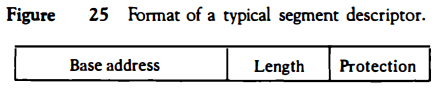
The content of each entry in the segment table or a segment register is called a descriptor.
A typical descriptor would contain, in addition to a base address field, one or two additional fields for protection purposes. A typical format for a segment descriptor is shown in Fig. 25.
The base address field gives the base of the page table address in a segmented-page organization or the block base address in a segment register organization.
This is the address used in mapping from a logical to the physical address. The length field gives the segment size by specifying the maximum number of pages assigned to the segment.
The length field is compared against the page number in the logical address. A size violation occurs if the page number falls outside the segment length boundary.
Thus a given program and its data cannot access memory not assigned to it by the operating system. The protection field in a segment descriptor specifies the access rights available to the particular segment. In a segmented-page organization, each
entry in the page table may have its own protection field to describe the access rights of each page.
The protection information is set into the descriptor by the master control program of the operating system. Some of the access rights of interest that are used for protecting the programs residing in memory are:
1. Full read and write privileges
2. Read only (write protection)
3. Execute only (program protection)
4. System only (operating system protection)
Full read and write privileges are given to a program when it is executing its own instructions. Write protection is useful for sharing system programs such as utility programs and other library routines.
These system programs are stored in an area of memory where they can be shared by many users. They can be read by all programs, but no writing is allowed. This protects them from being changed by other programs.
The execute-only condition protects programs from being copied. It restricts the segment to be referenced only during the instruction fetch phase but not during the execute phase.
Thus it allows the users to execute the segrnent program instructions but prevents them from reading the instructions as data for the purpose of copying their content.
Portions of the operating system will reside in memory at any given time. These system programs must be protected by making them inaccessible to unauthorized users.
The operating system protection condition is placed in the descriptors of all operating system programs to prevent the occasional user from accessing operating system segments.