General Shift Register
If the flip-flop outputs of a shift register are accessible then information entered serially by shifting can be taken out in parallel from the outputs of the flip-flops.
If a parallel load capability is added to a shift register then data entered in parallel can be taken Out in serial fashion by shifting the data stored in the register.
A register capable of shifting in one direction only is a unidirectional shift register. One that can shift in both directions is a bidirectional shift register
If the register has both shifts and parallel-load capabilities it is referred to as a universal shift register.
The most general shift register has the following capabilities:
A clear control to clear the register to 0
A clock input to synchronize the operations.
A shift-right control to enable the shift-right operation and the serial input and output lines associated with the shift right.
A shift-left control to enable the shift-right operation and the serial input and output lines associated with the shift left.
A parallel-load control to enable a parallel transfer and the n input lines associated with the parallel transfer.
'n' parallel output lines
A control state that leaves the information in the register unchanged in response to the clock.
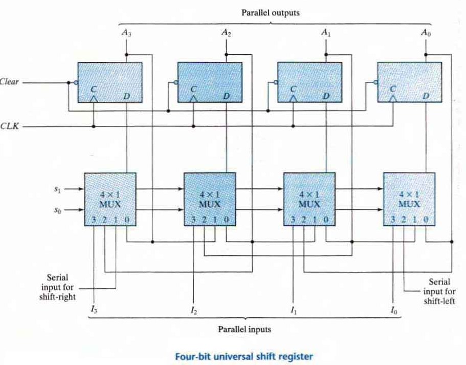
Universal Shift Register
The circuit consists of four D flip-flops and four multiplexers. The four multiplexers have two common selection inputs S1 and S0.
Every combination of S1 and S0 selects a particular input.
Operation of Universal Shift Register
When S1S0 = 00 , the present value of the register is applied to the D inputs of the flip -flops. This condition forms a path from the output of each flip-flop into the input of the same flip-flop so that the output recirculates to the input in this mode of operation. The next clock edge transfers into each flip-flop the binary value it held previously and no change of state occurs.
When S1S0 = 01, terminal 1 of the multiplexer inputs has a path to the D inputs of the flip-flops. This causes a shift-right operation, with the serial input transferred into flip-flop A3.
When S1S0 = 10, a shift left operation results in the other serial input going into flip flop A0.
When S1S0 = 11, the binary information on the parallel input lines is transferred into the register simultaneously during the next clock edge. Note that data enters MSB_in for a shift-right operation and enters LSB_in for a shift-left operation.
RIPPLE COUNTERS
A register that goes through a prescribed sequence of states upon the application of input pulses is called a Counter.
The sequence of states may follow the binary number sequence or any other sequence of states. A counter that follows the binary number sequence is called a binary counter. An n-bit binary Counter consists of n flip-flops and can count in binary from 0 through 2n - 1.
Counters are available in two categories:
Ripple counters: A flip-flop output transition serves as a source for triggering other flip-flops. So the C input of some or all flip-flops are triggered not by the common clock pulses but rather by the transition that occurs in other flip-flop outputs.
Synchronous counters: The C inputs of all flip-flops receive the common clock.
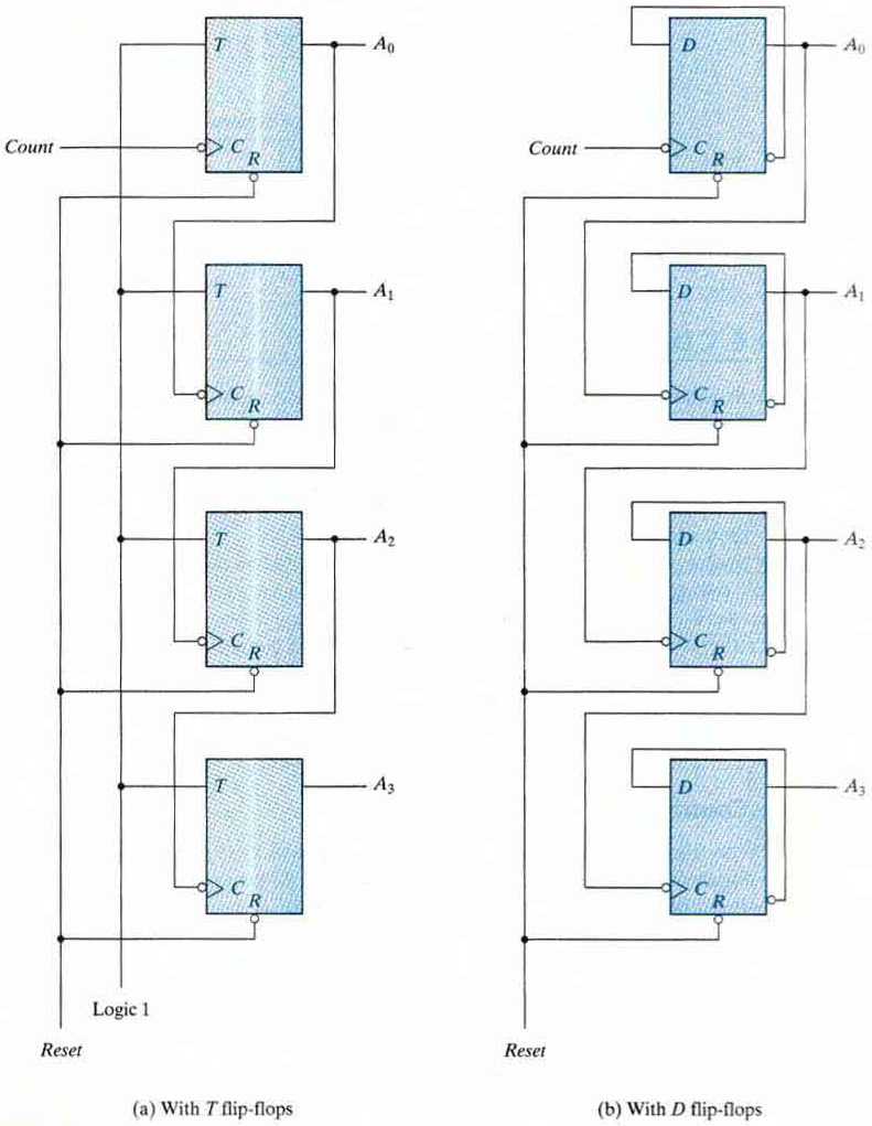
Binary Ripple Counter
A binary ripple counter consists of a series connection of complementing flip-flops with the output of each flip-flop connected to the C input of the next higher order flip-flop.
The flip-flop holding the least significant bit receives the incoming count pulses.
A complementing flip-flop can be obtained from a JK flip-flop with the J and K inputs tied together or from a T flip-flop.
A third possibility is to use a D flip-flop with the complement output connected to the D input. In this way the D input is always the complement of the present state and the next clock pulse will cause the flip-flop to complement.
The output of each flipflop is connected to the C input of the next flip-flop in sequence. The flip-flop holding the least significant bit receives the incoming count pulses.
Operation of the four-bit binary ripple counter
The count starts with binary 0 and increments by 1 with each count pulse input. After the count of 15, the counter goes back to 0 to repeat the count. The least significant bit A0 is complemented with each count pulse input.
Every time that A0 goes from 1 to 0 it complements A1, Every time that A1 goes from 1 to 0, it complements A2. Every time that A2 goes from 1 to 0, it complements A3 and so on for any other higher order bits of a ripple counter.
A binary counter with a reverse count is called a binary countdown counter. In a countdown counter, the binary count is decremented by 1 with every input count pulse. The count of a four-bit countdown counter starts from binary 15 and continues to binary counts 14, 13, 12, ... , 0 and then back to 15.
The least significant bit is complemented with every count pulse. Any other bit in the sequence is complemented if its previous least significant bit goes from 0 to 1.
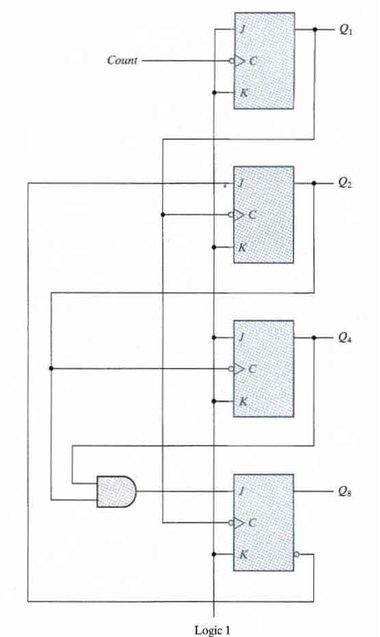
BCD Ripple Counter Or Decade Counter
A decimal counter follows a sequence of 10 states and returns to 0 after the count of 9. Such a counter must have at least four flip-flops to represent each decimal digit since a decimal digit is represented by a binary code with at least four bits.
The logic diagram of a BCD ripple counter using JK flip-flops has four outputs which are designated by the letter symbol Q with a numeric subscript equal to the binary weight of the corresponding bit in the BCD code.
The output of Q1 is applied to the C inputs of both Q2 and Q8 and the output of Q2 is applied to the C input of Q4.
The J and K inputs are connected either to a permanent 1 signal or to outputs of other flip-flops.
Flip-Flop transitions:
Q1 changes state afte r each clock pulse.
Q2 complements every time Q1 goes from 1 to 0 as long as Q8 = 0. When Q8 becomes 1 Q2 remains at 0.
Q4 complements every time Q2 goes from 1 to 0.
Q8 remains at 0 as long as Q2 or Q4 is 0. When both Q2 and Q4 become 1 Q8 complements when Q1 goes from 1 to 0. Q8 is cleared on the next transition of Q1.
BCD counter:
The BCD counter is a decade counter since it counts from 0 to 9.
To count in decimal from 0 to 99, we need a two-decade counter. To count from 0 to 999 we need a three-decade counter.
Multiple decade counters can be constructed by connecting BCD counters in cascade, one for each decade. A three-decade counter is shown below. The inputs to the second and third decades come from Q8 of the previous decade.
When Q8 in one decade goes from 1 to 0 it triggers the count for the next higher order decade while its own decade goes from 9 to 0.