Arduino Uno
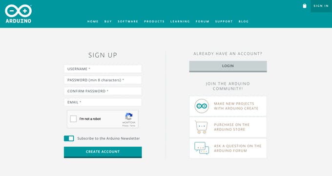
Step 1: Sign up to Arduino - Create a new Arduino Account Apply Now. Complete the registration form, then hit the ‘Create Account ’ button. Then activate the account.
Step 2: After signing up you can either use the Arduino Wed Editor IDE Download Now or download Arduino IDE. Arduino Web Editor IDE is used for programming of Arduino uno boards and requires no installation.
Step 3: If internet isnt reliable then use Arduino IDE for offline programming of Arduino uno boards Download Now.
Step 4: Connect the Arduino uno to the PC using connector which is a printer wire.
Step 5: Once Arduino board is connected open Arduino Web Editor IDE or Arduino IDE
Arduino Web Editor IDE - Layout
Arduino Web Editor IDE is shown below.
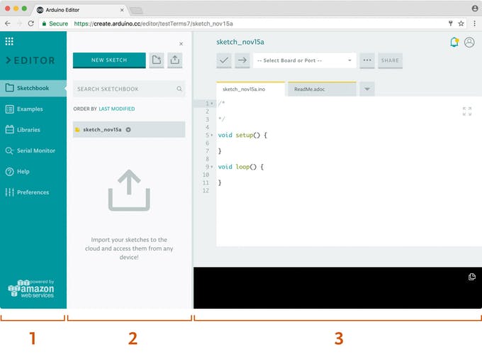
The first column lets you to navigate between:
Your Sketchbook: a collection of all your sketches (’sketch ’ is what programs you upload on your board are called).
Examples: read-only sketches that demonstrate all the basic Arduino commands (built-in tab), and the behavior of your libraries (from the libraries tab)
Libraries: packages that can be included to your sketch to provide extra functionalities
Serial monitor: a feature that enables you to receive and send data to your board via the USB cable
Help: helpful links and a glossary about Arduino terms
Preferences: options to customize the look and behavior of your editor, such as text size and color theme
When selected, every menu items shows its options in a side panel (second column).
The third column, the code area, is the one you will use the most. Here, you can write code, verify it and upload it to your boards, save your sketches on the cloud, and share them with anyone you want.
Arduino Web Editor IDE - Program - Blinking LED
Now that you’ve set up your online IDE, let’s make sure your computer can talk to the board; it’s time to make sure you can upload a program.
Double check if the Web Editor is displayed the way you like, check the Preferences panel for a few options
Connect your Arduino or Genuino board to your computer. Boards and serial ports are auto-discovered and selectable in a single dropdown. Pick the Arduino/Genuino board you want to upload to from the list.
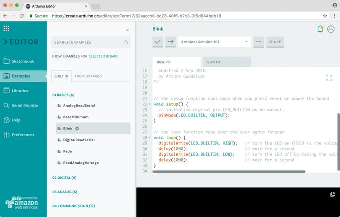
Let’s try an example: Choose ‘Examples ’ on the menu on the left, then ‘Basic ’ and ‘Blink ’. The Blink sketch is now displayed in the code area.
To upload it to your board, press the ‘Upload ’ button (arrow right) near the dropdown. A ‘BUSY ’ label replaces the buttons during code verifying and uploading. If the upload is successful, the message “Success: Done uploading ” will appear in the bottom output area.
Once the upload is complete, you should then see on your board the yellow LED with an L next to it start blinking. If this is the case congratulations! You have successfully programmed your board to blink its on-board LED!
Arduino Desktop Editor IDE - Program - Analog Serial Monitor
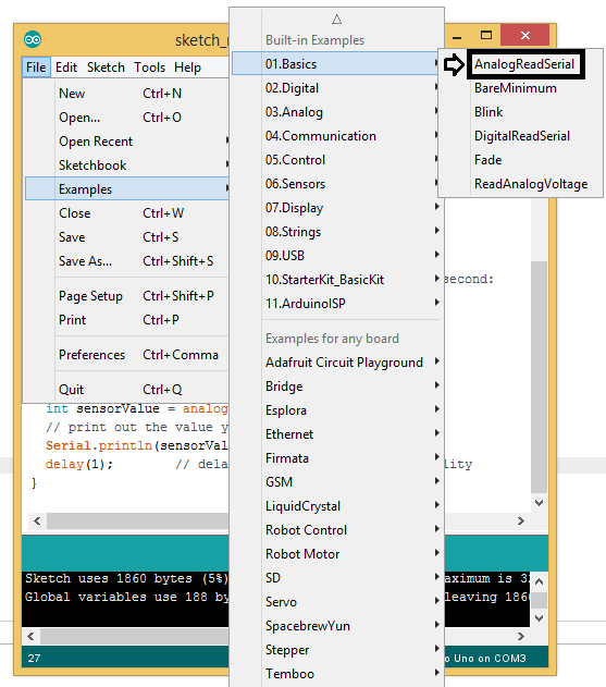
Step 1: Open the Arduino Desktop IDE. Click File in the top Menu bar , then 01 Basics then AnalogReadSerial
Step 2: You will see a new window open and the program already written for you. Code is shown below.
/*
  AnalogReadSerial

  Reads an analog input on pin 0, prints the result to the Serial Monitor.

  This example code is in the public domain.

  http://www.arduino.cc/en/Tutorial/AnalogReadSerial
*/

// the setup routine runs once when you press reset:
void setup() {
  // initialize serial communication at 9600 bits per second:
  Serial.begin(9600);
}

// the loop routine runs over and over again forever:
void loop() {
  // read the input on analog pin 0:
  int sensorValue = analogRead(A0);
  // print out the value you read:
  Serial.println(sensorValue);
  delay(1);        // delay in between reads for stability
}
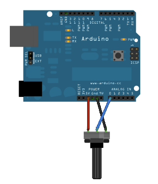
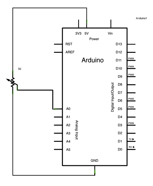
Step 3: Apparatus required are potentiometer, arduino uno board and printer cable. Printer cable connects arduino board to PC.
Step 4: Connect potentiometer as shown in below diagrams. The Potentiometer has three wire outputs (Red, black, blue/yellow). Red is for VCC (power supply), Black is for Ground, Blue/yellow is for input signal. An optional white wire is also found for No close (NC). You can ignore NC.
Step 5: Once connections are made. Click on upload button to send the sketch (arduino program) to the board. Upload button is shown in red arrow below.
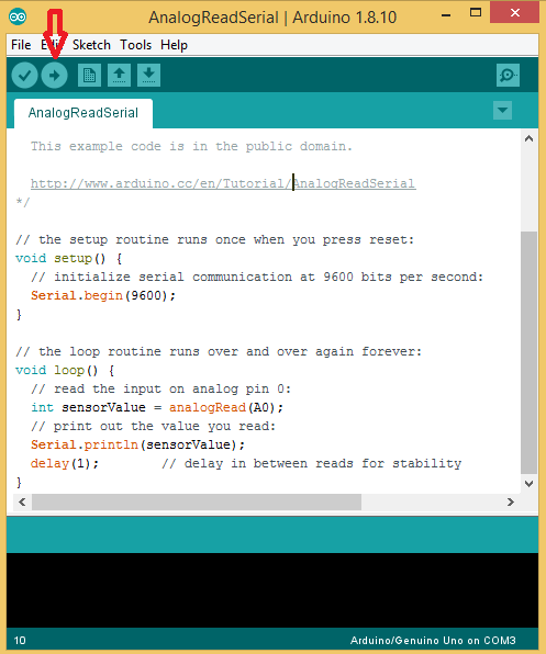
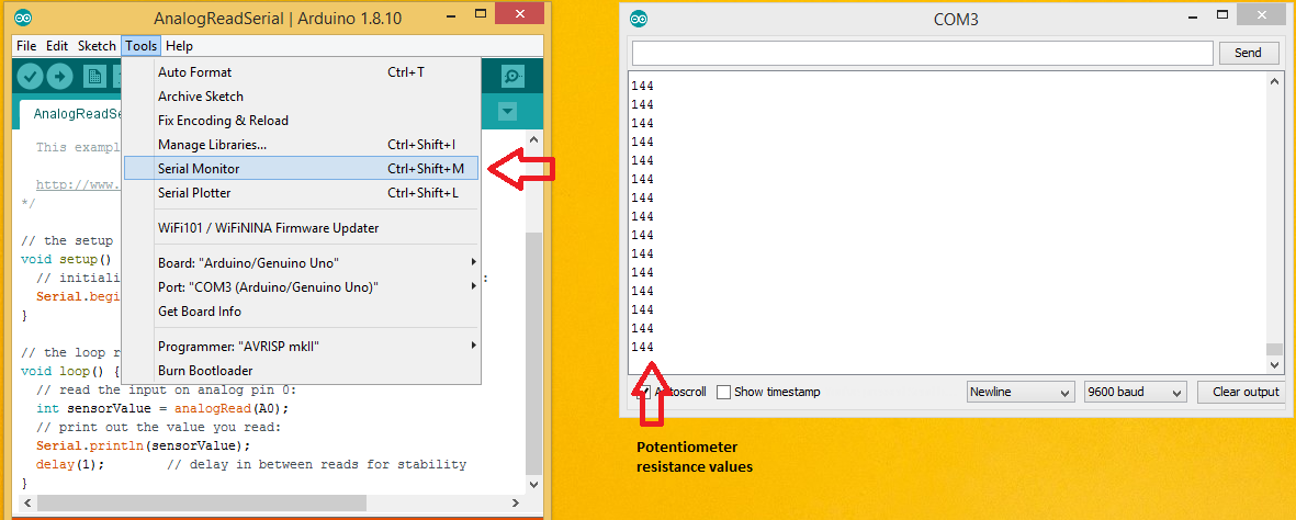
Step 6: If arduino uno is connected properly then program will be transmitted. To check output go to Tools -> Serial Monitor. You can change potentiometer value by turning knob.
Explanation of Program - Analog Serial Monitor
Two main functions of arduino uno. setup() and main(). setup() is for initialization and loop() runs over and over again.
// the setup routine runs once when you press reset:
void setup() {

// initialize serial communication at 9600 bits per second:
  Serial.begin(9600);

}
analogRead() takes as argument port number of any analog port of arduino uno. Arduino uno has A0, A1, A2, A3, A4 and A5 analog input ports. Serial.println() is used to display on serial monitor.
// the loop routine runs over and over again forever:
void loop() {

  // read the input on analog pin 0:
  int sensorValue = analogRead(A0);
  // print out the value you read:
  Serial.println(sensorValue);
  delay(1);        // delay in between reads for stability

}