Program: Seven segment display
A seven segment display is used to display numbers 0-9 and A to F.
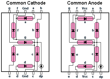
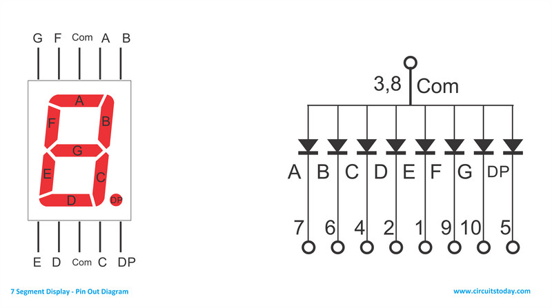
The internal pin connections of seven segment display is shown below.
There are two types: comman anode and comman cathode. Here we use a comman cathode type SSD.
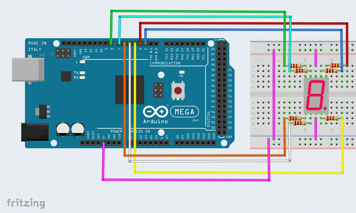
Connections are made as shown below. Board used is arduino mega. Pin 3,8 are connected to VCC of the board as SSD is comman anode type. If it had been comman cathode type SSD pin 3,8 would be at ground.


void setup()
{
 pinMode(2,OUTPUT);
 pinMode(3,OUTPUT);
 pinMode(4,OUTPUT);
 pinMode(5,OUTPUT);
 pinMode(6,OUTPUT);
 pinMode(7,OUTPUT);
 pinMode(8,OUTPUT);

}

void loop()
{
  // loop to turn leds od seven seg ON

  for(int i=2;i<9;i++)
  {
    digitalWrite(i,HIGH);
    delay(600);
  }

  // loop to turn leds od seven seg OFF
  for(int i=2;i<9;i++)
  {
    digitalWrite(i,LOW);
    delay(600);
  }


  delay(1000);

}
Program: Seven segment display part 2
We use a comman anode type SSD and alternate turn it on and off.
Connections are made as shown below. Board used is arduino mega. Pin 3,8 are connected to VCC of the board as SSD is comman anode type. If it had been comman cathode type SSD pin 3,8 would be at ground.
void setup()
{
  // define pin modes

 pinMode(0,OUTPUT);
 pinMode(1,OUTPUT);
 pinMode(2,OUTPUT);
 pinMode(3,OUTPUT);
 pinMode(4,OUTPUT);
 pinMode(5,OUTPUT);
 pinMode(6,OUTPUT);

}

void loop()
{
high();
delay(1000);
low();
delay(1000);
}
void high()
{
  for(int i=0;i<7;i++)
  {
    digitalWrite(i,HIGH);
  }
}
void low()
{
  for(int i=0;i<7;i++)
  {
    digitalWrite(i,LOW);
  }
}
Program: Seven segment display part 3
We use a comman cathode type SSD and use it count numbers.
Connections are made as shown below. Board used is arduino mega. Pin 3,8 are connected to VCC of the board as SSD is comman anode type. If it had been comman cathode type SSD pin 3,8 would be at ground.
// make an array to save Sev Seg pin configuration of numbers

int num_array[10][7] = {  { 0,0,0,0,0,0,1 },    // 0
                          { 1,0,0,1,1,1,0 },    // 1
                          { 0,0,1,0,0,1,0 },    // 2
                          { 0,0,0,0,1,1,0 },    // 3
                          { 1,0,0,1,1,0,0 },    // 4
                          { 0,1,0,0,1,0,0 },    // 5
                          { 0,1,0,0,0,0,0 },    // 6
                          { 0,0,0,1,1,1,1 },    // 7
                          { 0,0,0,0,0,0,0 },    // 8
                          { 0,0,0,1,1,0,0 }};   // 9

//function header
void Num_Write(int);

void setup()
{
  // set pin modes
  pinMode(2, OUTPUT);
  pinMode(3, OUTPUT);
  pinMode(4, OUTPUT);
  pinMode(5, OUTPUT);
  pinMode(6, OUTPUT);
  pinMode(7, OUTPUT);
  pinMode(8, OUTPUT);


}

void loop()
{

  //counter loop

  for (int counter = 10; counter > 0; --counter)
  {
   delay(1000);
   Num_Write(counter-1);
  }
  delay(3000);
}

// this functions writes values to the sev seg pins
void Num_Write(int number)
{
  int pin= 2;
  for (int j=0; j < 7; j++) {
   digitalWrite(pin, num_array[number][j]);
   pin++;
  }
}
Program: Seven segment display part 4
We use a comman anode type Seven Segment Display and use it display number ZERO.
Connections are made as shown below. Board used is arduino mega. Pin 3,8 are connected to VCC of the board.
int seg_a = 2; // declare the variables
int seg_b = 3;
int seg_c = 4;
int seg_d = 5;
int seg_e = 6;
int seg_f = 7;
int seg_g = 8;
int seg_dp = 9;

void setup() {
  pinMode(seg_a,OUTPUT); // configure all pins used to outputs
  pinMode(seg_b,OUTPUT);
  pinMode(seg_c,OUTPUT);
  pinMode(seg_d,OUTPUT);
  pinMode(seg_e,OUTPUT);
  pinMode(seg_f,OUTPUT);
  pinMode(seg_g,OUTPUT);
  pinMode(seg_dp,OUTPUT);
}

void loop() {

  digitalWrite(seg_a,LOW);
  digitalWrite(seg_b,LOW);
  digitalWrite(seg_c,LOW);
  digitalWrite(seg_d,LOW);
  digitalWrite(seg_e,LOW);
  digitalWrite(seg_f,LOW);
  digitalWrite(seg_g,HIGH);
  digitalWrite(seg_dp,HIGH);

}