Getting started with NodeMCU / ESP8266
The NodeMCU is an Arduino-compatible board that features the ESP8266 at its core. It became popular because it is a WiFi-ready microcontroller by itself - no need for an Arduino. Its basically an SoC (System on Chip)
A System on a Chip or System on Chip(SoC) is an integrated circuit that integrates all components of a computer or other electronic systems.
ESP8266 chip having Tensilica Xtensa® 32-bit LX106 RISC microprocessor which operates at 80 to 160 MHz adjustable clock
There’s also 128 KB RAM and 4MB of Flash memory
As the operating voltage range of ESP8266 is 3V to 3.6V
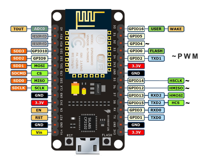
The ESP8266 NodeMCU has total 17 GPIO pins
ADC channel – A 10-bit ADC channel.
UART interface – UART interface is used to load code serially.
PWM outputs – PWM pins for dimming LEDs or controlling motors.
SPI, I2C & I2S interface – SPI and I2C interface to hook up all sorts of sensors and peripherals.
I2S interface – I2S interface if you want to add sound to your project.
The board has a LED indicator which is user programmable and is connected to the D0 pin of the board.
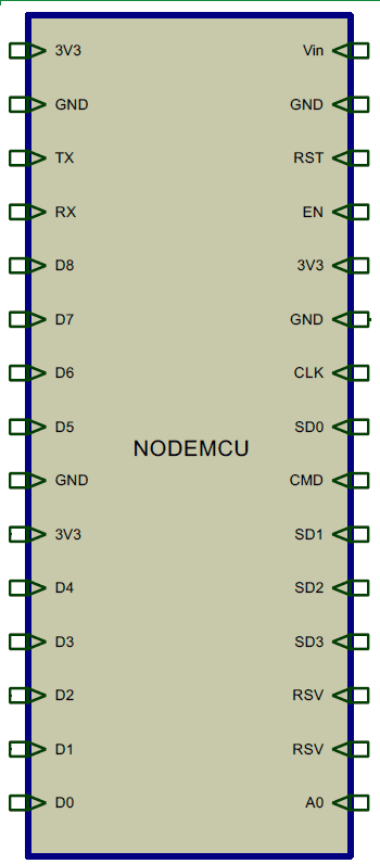
There are four power pins viz. one VIN pin & three 3.3V pins.
GND is a ground pin of ESP8266 NodeMCU development board.
I2C Pins are used to hook up all sorts of I2C sensors and peripherals in your project.
ESP8266 NodeMCU has 17 GPIO pins which can be assigned to various functions such as I2C, I2S, UART, PWM, IR Remote Control, LED Light and Button programmatically.
ADC Channel - The NodeMCU is embedded with a 10-bit precision Analog to Digital Converter.
UART Pins ESP8266 NodeMCU has 2 UART interfaces, i.e. UART0 and UART1, which provide asynchronous communication (RS232 and RS485), and can communicate at up to 4.5 Mbps.
Control Pins are used to control ESP8266. These pins include Chip Enable pin (EN), Reset pin (RST) and WAKE pin.
EN pin – The ESP8266 chip is enabled when EN pin is pulled HIGH. When pulled LOW the chip works at minimum power.
RST pin – RST pin is used to reset the ESP8266 chip.
WAKE pin – Wake pin is used to wake the chip from deep-sleep.