I2C Communication line
The I2C library or the wire library supports what's called I2C communication.
One of the things that you often want to do in a system when you have a micro controller is to connect it to another integrated circuit.
You want to connect your micro controller to other chips. So you can talk to those chips and tell them what to do, grab data from them and so forth.
These chips, when they communicate there are several different protocols one is called I2C. I2C communication protocol is a serial protocol and it's a synchronous protocol.
So serial means it sends data over only one wire. Data is only traveling over one wire. This is good because they save pins . In this case you need two total pins, but data is only going across one.
The downside of that is that since it's serial it's sending one bit at a time. So it takes longer, it's slower. If you send eight bits in parallel that's a lot quicker than sending one at a time.
Also, it's a synchronous protocol. What that means is that if there are two communicating entities, two integrated circuits, talking on I2C, they need to share the same clock.
They need to share it so they can synchronize with each other. Based on the clock, the receiver knows when the sender's gonna be sending data. The receiver knows when to read the bus and sender knows when to write.
There are also in I2C multiple masters and multiple slaves. Basically, the master is the one who starts all the communications and the slave is the one who waits for communications,
Bitwidth is fixed. The number of bits traveling between these two or any number of devices on an I2C bus is fixed. There is the data signal and the clock signal, just two. And it's independent of the number of slaves.
There are other protocols where every slave you have to add more bits. But I2C you can have as many slaves as you want, or up to the limit that they enforce. And you can, and it's the same number of bits, two bits.
In I2C we have two wires SDA (serial data) and SCL (serial clock). SDA is the data, that's the line where the data's gonna travel. And SCL's a clock that's used to synchronize all the devices.
Both lines, SDA and SCL, are open drain, that means is that they are connected to power through a big resistor i.e 10kohms or higher. Hence, they're pulled up high by default.
That means if let's say there are lots of different I2C communicating entities on this bus. They're wired to the SDA and SCL lines. But nobody is talking on the bus. So none of these components are driving those two wires high or low. Because they're connected to power through a big resistor, they will automatically go high.
Now, if any one of these communicating entities wanna force a zero into the line, they can. They can pull it down to a zero but if nobody's talking on the bus, the state of the bus is still defined.
You always know that it's gonna be high by default. And that's actually useful in the protocol to know, that the state is always either zero or one. It's not some random intermediate value.
A master is a nodeon the bus that initiates and terminates transmission. So when transmission starts the master starts it. When it stops the master stops it. Also it generates the clock SCL, so the clock is generated by the master.
The Slave is addressed by the Master. So the Slave basically waits until the Master starts communication and until the Master stops communication.
These transmissions are either write transmissions or read.
Now, in addition to that, there's also transmitter and receiver which are orthogonal to master and slave.
So the transmitter is whatever node is putting data onto the bus. And the receiver is whatever date known as receiving data from the bus.
The master can be the transmitter, it can be the master that starts transmissions and puts data on the bus. The master can be the receiver too.
So master may order the slave to give it information. So the master can also be the receiver, and the slave can be the transmitter or receiver also.
Every node is either a master or a slave, and can also be either a receiver or a transmitter
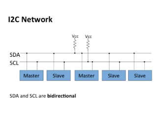
Below is a picture of what the bus network will typically look like. Each one of those blue blocks is labelled master, slave.
Each one of those connect to the same set of two lines SDA and SCL. So SDA and SCL are common to all the masters and slaves, all the nodes on the bus.
SDA and SCL are bidirectional. So you can talk in two directions, you can talk, data can go either way along those wires. From left to right, right to left, whatever.
Also notice that the two lines SDA and SCL are wired to Vcc, meaning power through big resistors. Those resistors aren't labeled, but they are presumably big. 10k ohms or something like that.
I2C Communication line - transaction line
An I2C transaction, structure of a transaction, means the sequence of zeros and ones that you expect to see on the two lines- The data line and the clock line, In order to send data, to write data or read data,
In I2C, every transaction is either a write transaction, meaning the master is writing to the slave, sending data to the slave. Or it's a read-transaction, meaning the master is gonna receive data from the slave.
Every transaction starts off with a start condition. A start condition is a condition on the two signals, the SDA and SCL that indicates the beginning of the transaction.
Once the start condition happens the master creates the start condition on the bus. And then the slaves are all listening to the bus. And they look for the start condition, when they see the start condition they know a transaction is about to start.
After the start condition is sent, then you gotta send the address. So every slave on this bus has an address, a known address. And the addresses are seven bits long.
There's also another variance to this protocol where addresses can be ten bits long, but right now let's say seven bits long.
So the master, when it's sending data to a particular slave, starting a transaction with a particular slave. It has to send that seven bit long address on the wires, one clock cycle at a time on the SDA line.
Say the address is 0000001. It puts that sequence on the SDA line. One clock cycle at a time, one SCL. So the first SCL clock, you'll have a zero. Next one, you'll have a zero, and so on. It puts them on one at a time. And then, in addition to the address, there's one more bit that is a direction bit. So all together, the address and direction make up a byte, that's eight bits all together.
And the direction is, it's just a single bit, zero or one. It indicates whether this is a read transaction or a write transaction.
At the point when the address and the direction are being sent, the slaves are all listening for the address. They receive the address bits one at a time. Then once they receive all seven, they compare those address bits to their own address. And if it's a match, then they continue to interact on this transaction. And if it's not a match, then all the rest of the slaves are aware it's not a match. They just go to sleep and forget about this transaction and wait until it's over.
Once you've sent the address and the direction, then there's a data byte or a set of data bytes that can be sent. Now, if this is a right transaction, then you send as many data bytes as you wanna write.
If this is a read transaction, then what happens is the slave has to send bytes back, as many bytes as are needed to be read. Until finally, there's a stop condition.
And it sets a stop condition, sends that on the data line i.e., the SDA line.
And the slave recognizes that, and then stops the transmission.
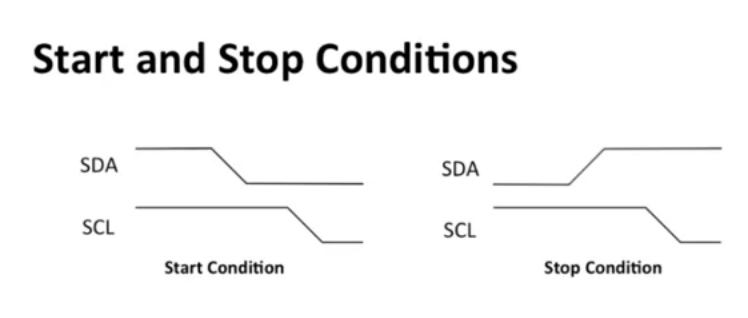
Graphically the structure - for start and stop of transactionn are given below
The SDA line - if there is a falling edge on that line ( high to low). If that happens while the SCL line, the clock line, is high, then that's a start condition.
Now, stop conditions is the reverse. The SDA line goes from zero to one while the clock line, the SCL line, is high. So that's a stop condition.
So when the master wants to start a communication - the master drives SDA from high to low while SCL high and if it wants to stop the communication, then it just does the opposite. It drives SDA from low to high while the SCL is high.
So start condition is falling transition on SDA while SCL=1.
And stop condition is a rising transition on SDA while SCL=1.
I2C Communication line - sending bits
I2C protocol is about sending one bit at a time. First you're sending the address bits, the direction bits. Then you're sending the data bits and so on. So you have to be able to send one bit at a time on these lines.
Remember that there are two wires, SDA and SCL. And the data, whatever bit you're gonna send, that's gonna go on the SDA line. The SCL line is a clock, so its going up and down.
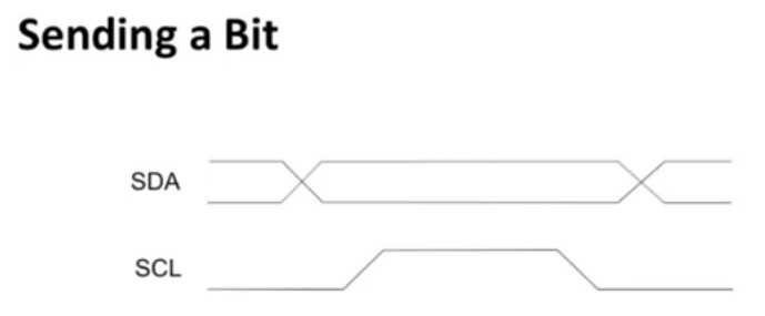
The above diagram is showing how sending a bit how a might look. Now you can see at the bottom, the SCL that's low then high then low, that's one clock pulse. The SDA line however, that can change from zero to one, one to zero. Zero is low and one is high.
Now in the diagram if you want to send a zero through the SDA. The steps are that the SDA will be made high while the SCL is at the rising edge. Similarly, if you want to send zero then the SDA will be made low while the SCL is rising. In short, only while the SCL is rising can you send bits 0/1
Second rule is that while the SCL is high the value of SDA does not change.
They only time you can break that rule is if you're doing a start condition or a stop condition. Those conditions explicitly violate those rules
A start condition is where the SDA goes low while the clock is high. And a stop is where it goes high while the clock is high.
But if you're sending data, you're sending actual data, then the rule is that the SDA line has to be held constant the whole time that the clock is high.
An acknowledge bit - So you do a start condition. Then you send a byte. The first seven bits of the byte are the address. And then the next one bit is the direction. But all together that's a chuck of eight bytes.
Now, what happens is, after a sequence of eight bits is sent, the receiver has to acknowledge that it received the eight bits. Now this is for error checking essentially, because you never know what kind of error might have happened in communication.
So if it didn't receive the eight bits, then you need to restart your communication.
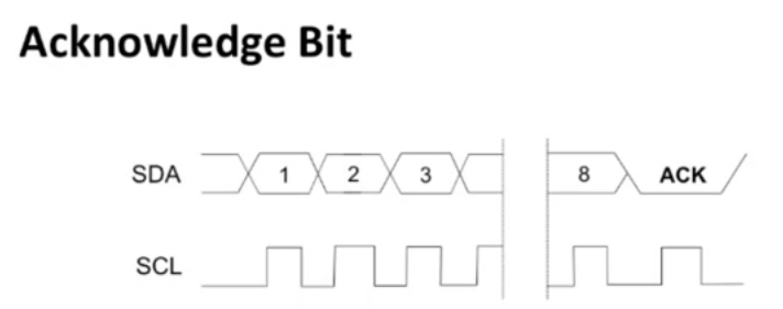
So after every chunk of eight, the receiver has to transmit what's called an acknowledge bit.
Now what that means is, let's say we've got the SDA line, SCL line. SCL's pulsing high low and SDA, somebody, say the master, is transmitting to the slave
So, once the sender sends out all eight of these bits, for one SCL clock pulse, the sender does not drive the SDA line. It's up to the receiver at that point to pull the SDA line low. That's called acknowledge.
See where it says ACK, notice that the SDA line is low when it says ACK.
So for that SCL clock pulse, the receiver has to pull that SCL line low and acknowledge. If it doesn't do that then the sender has to assume that something went wrong and restart the communication.
So after each byte is sent, the receiver must acknowledge by pulling that SDA line low.
And once the transmitter has to release the SDA line so the receiver can pull it low. It must be low for one pulse of the clock or else the transmissions aborted.
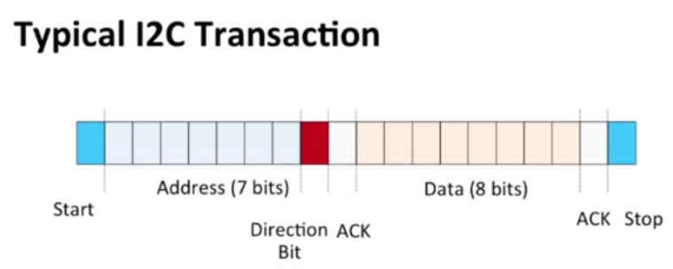
So typical I2C transaction, a very short I2C transaction looks like overall as given below.
There's a start condition, that's how you initiate everything with the start condition. Then you send 8 bits, the address bits, 7 address bits plus a direction bit. So that's 8 bits.
Then there's an acknowledgement to ACK right there.
Then you send 8 more data bits. And then there's another acknowledge, and then you can stop.
You could have many data bytes
So this is sortof a typical I2C transaction, what it looks like on the SDA lines. Each slave has a unique 7 bit address. Direction is 0 is a right, 1's a read. And ACK happens after every byte.
I2C Communication line - Wire Library
The Wire Library is used to access I2C.
To start off using library, like with all libraries you get start off with a hashtag include with appropriate hashtag.
#include<wire.h>
Then to initialize the library, start off all the I2C operations, you call wire.begin. This initializes the I2c hardware.
In the micro controller, the ATmega328, it has hardware dedicated to I2C
And so that hardware is initialized by calling Wire.begin. Now, if you call Wire.begin with no arguments, that makes the Arduino the Master.
But if you call Wire.begin with an address as an argument, some number between 0 and 127, then that makes the Arduino a Slave.
Master Communication.
start the communication,
send a bunch of data.
end the communication.
One thing to note is that data is put into a buffer before sending. So, what I mean is, inside the ATmega328 there is a buffer for the I2C data that you're going to send. The whole transaction is done at once. Basically the whole buffer is dumped onto the lines.
Say you want to send 10 bytes. All 10 bytes are put into a buffer and then, when you end the transmission, when you call end transmission, it actually sends those 10 bytes on the SDA and SCL lines.
#include<wire.h>

#define ADDR 1;
void setup()
{
Wire.begin();
Wire.beginTransmission(ADDR);
Wire.write(2);
Wire.write(2);
Wire.endTransmission(stop);
}
To start off, we say wire.beginTransmission(address), and this initializes communication and tells it what that address is it's gonna be sent.
Now, then you say, you write data You Wire.write() into basic writes data.
And in transmission, it basically it transmits the data in the buffer, and creates a stop condition.
So when you call end transmission, it takes all the data that you wrote into the bus, it creates a start transmission, a start condition. It sends the address. Then it sends all the data in the buffer. And then it creates the end condition.
So basically, all your transmissions are going to happen like that.
There's going to be a beginTransmission, then a bunch of writes if you're doing write transaction. And then a end transmission.
ADDR - Slave address to send data to.
So we say wire.begin to initialize the I2C hardware. Then wire.begintransmission to the address. Then I'll say wire.write(2) wire.write(3) if we are sending two bytes, a two and a three. And then, wire.endTransmission and (stop) and that just causes all the data to be sent in the format in I2C.
I2C Communication line - Wire Library Master communication
int sum=0;
Wire.requestFrom(ADDR,2);
while (Wire.available())
{
    sum += (int) Wire.read();
}
Let's say the master wants to do a read, so the master wants to grab data from the slave.
There are some different function calls for that. First is this Wire.requestFrom().
The master initiates a read request from the slave.
Now this take three arguments. One is the address of the slaves, so that's gonna be the first argument. The second is the number of bytes to read, the number of bytes being requested. And the third argument is an optional argument, a stop argument.
The word stop you can add in there to release the bus after you're done.
So, releasing the bus means asserting a stop condition.
If it asserts a stop condition, then it releases a bus. It's basically giving up access to the bus and saying look, any other master can now take over this bus if they want to use it to communicate.
Where if you don't do that stop condition, then this master is free to make more requests.
Wire.read() actually reads that data that's received, reads one byte. Wire.read() reads exactly one byte. So what happens is, when you do a Wire.requestFrom(), it request the data and the data eventually, in the slave time, is received
So once the data is received by the master, it's put into a buffer on the master. And then the master, in order to access that data, has to call Wire.read() to read the bytes one at a time from that receive buffer.
Another function called Wire.available(), which returns a number of bytes waiting.
You need this for a couple of things. One main reason is that even though the master requested a certain amount of data, maybe the master requests ten bytes, the slave may not give ten bytes, for one reason or another.
So, Wire.available() is a function the master can call to see if there's data available in the receive buffer that it can read.
int sum=0;
Wire.requestFrom(ADDR,2);
while (Wire.available())
{
    sum += (int) Wire.read();
}
In above program: the master requests from a slave two bytes
To start off, int sum = 0. wire.requestFrom(), the address, whatever the address of the slave is, comma 2. As master is requesting two bytes
So while Wire.available() which means while there is data waiting, you say sum +=, so add to the sum.
Now, we code Wire.read() to grab the byte, we cast it to an int. Then add it and store result in sum.
I2C Communication line - Wire Library Slave communication
So far we've been looking at the master, and how it operates, how it does the transmit, how it does the receive. Now let's look at it from the slave point-of-view.
So let's say the arduino is actually acting as a slave in the I2C communication. A slave remember has to wait for a transmission, it can't initiate anything. It has to sit there and wait.
Now, waiting is conceivably a problem because how does the machine wait? One way is to use what is called the busy wait loop, now busy wait loop is immensely wasteful. Basically it's just a while loop.
A while loop that's just infinitely checking to see if a request has been received.
Now the reason why this is wasteful is because the slave can't do anything until the request is received. So let's say it runs for an hour before a request is received. For that hour, it's just sitting there in a wait loop, while loop doing nothing. This is called busy waiting.
That's a waste. So we don't want to do that. We would like the arduino or the microcontroller in general to be doing things.
And then every once in awhile maybe a request is made and it has to wake up and handle that request.
So we want the processor who is acting as a slave to be continuous normal operation and just be basically interrupted periodically when it has to deal with I2C.
So what we use for that is called callback functions and this is a general thing, used not just in this domain but in lots of different domains.
A callback function is a function that is called when an event occurs. So while the event is not occurring, the processor can be doing whatever it's doing
So we use callback functions for both types of transmissions.
void receiveFunc(int byteNum)
{
int i, sum = 0;
for (i=0; i<byteNum;i++)
 {
    sum+=Wire.read();
 }
Serial.print(sum);
}
Wire.onReceive(receiveFunct);
As shown in the above code for instance, we've got Wire.onReceive():. Wire.onReceive(): is a function that identifies the function called when the slave receives data from a master.
So as the master initiates a write transaction, then the slave is going to have to receive data.
So when the master initiates the write transaction, a callback function is called on the slave.
And Wire.onReceive, names the function that is gonna be called when data is being received by the slave.
Wire.onRequest, and this names the function that is called when the slave receives a read request.
void transmitFunc(void)
{
    Wire.write(SAMPLE_DATA_BYTE);
}
Wire.onRequest(transmitFunct);
Now note that onReceive and onRequest are not themselves the functions that handle the receiving and the requesting , they just provide the names of those functions.
the function called receiveFunct which is the arguments of Wire.onReceive. That function is gonna be called to do the receiving of the data.
void receiveFunc(int byteNum)
{
int i, sum = 0;
for (i=0; i<byteNum;i++)
 {
    sum+=Wire.read();
 }
Serial.print(sum);
}
Wire.onReceive(receiveFunct);
So, when the slave gets a write request from the master. All it does, is it takes all of the data that's being written, it adds it up into its sum and then prints it on its serial output.
So note that this receiveFunct takes one argument.
That argument is an integer, that is the number of bytes that's received. So when you write this functions, receiveFunct, it can have whatever name you want, but that function has to take one argument, which is the number of data bytes that have been received.
Now for transmission. So let's say the slave instead of receiving a write transaction request from the master it gets a read.
For this you can Wire.onRequest(transmitFunct).
void transmitFunc(void)
{
    Wire.write(SAMPLE_DATA_BYTE);
}
Wire.onRequest(transmitFunct);
So, transmitFunct is gonna be the name of the function that's going to do this transmission. So, since we're passing that name as an argument to the onRequest function that ties it to the request event.
When the event happens, the slave receives this read request. Then it call transmitFunct and if you look at the transmitFunct at the top. All that does is it just calls write, it sends some data.
In this transmission function, this callback function called transmitFunct. It has to take no arguments and returns nothing which is void and it should take no arguments.