General Purpose Input Output Pins
General Purpose Input/Output Pins on the Raspberry Pi B+ is given below. A layout of what the Raspberry Pi's pins look like.
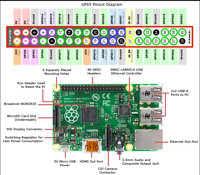
Now there's several different Raspberry Pis, we're using the Raspberry Pi B+, which has more pins, it actually has 40 of these pins.
And so if you look at the picture, there are 40 pins, two rows, 20 pins each row. There are other Raspberry Pis, like the Raspberry Pi B and the Raspberry Pi A, and those have 26 pins.
There are a lot of pins, two rows of pins. And this is similar to the Arduino, the Arduino had the pins on the sides.
Raspberry Pi has them all together in one block on one side of the board. So if you look at the pins, you could generally group them into the dedicated pins, dedicated power and ground pins.
So several of these pins, all they do is output power and ground, which you can use to interface with other devices. So say you have a breadboard, wire up a circuit, you need power, you need ground, you wire them to these pins. So that it's a common power and ground.
Remember, the Raspberry Pi pins run at 3.3 volts, so 0 to 3.3 volts. So you got several pins, two pins actually, pins 1 and 17 are 3.3 volts, they just supply 3.3 volts. You also have pins that supply 5 volts, pins 2 and 4 supply 5 volts.
You need that because there's still a lot of 5 volt devices out there that need 5 volts, so the board supplies that too. Although remember that the output pins in the Raspberry Pi are at 0 and 3.3 volts. And when you take inputs, they've gotta be 0 and 3.3 volts. You can't have 5 volts coming in or going out.
But it supplies 5 volts for other parts in the system that you might wanna be running that need 5 volts.
And then there are several ground pins, 6, 9, 14, 20, 30, and 39 are all ground pins that are on the board.
General purpose, GPIO is just a pin that can be used as an input or an output, and this is the same as on the Arduino
Notice the number of the PINs, there are two different names for these pins. You can call them 3, 5 and 7, or you can call them GPIO2, GPIO3, or GPIO4. So the pins - dedicated ones are GPIOs and that means that you can control them programmatically.
There's GPIO2, if we look at pin 3. It's labeled GPIO2 and then SDA1I2C. And then GPIO3 is labeled SCL1I2C.
They've got two names, so we'll call those multi-function pins. They can serve multiple purposes. They can act as either GPIOs where as a programmer you could just access them directly. Or they could serve another, an alternate function based on their alternate name
So just from the nameof these pins we can already tell what their function is. So this is SDA and SCL - the communication pins for the I2C protocol. So those two pins are actually part of the I2C protocol
Notice pin 7 is just GPIO4, and it doesn't serve any special function, it's just general purpose I/O.
UART is serial protocol, single bit, one bit at a time is being transferred. So these two pins, they're GPIO14 and 15 but they are also UART0_TXD and RXD. So TX stands for transmit, and RX stands for receive.
If you remember UART, basically you're sending one bit at a time, and TX is the transmission pin. So if you wanna send serial bit, serial data, UART data from the Raspberry Pi to another device, you send it on the TX, and on the receiving end, you receive it on the RX.
That's the common way to do it, TX for transmission, RX for receiving.
So if you say had another Raspberry Pi, you could take the TX and RX of this one, connect it to the TX and RX of the other one, and they can talk to each other.
Protocol pins in Raspberry Pi 3B+
Multi-function pins that have a function that's dedicated to communication protocols with other devices or other chips.
So a couple of these pins are for I2C communication protocol.I2C, is a serial communication protocol between, generally used between two chips or two devices that are relatively close, that can share a clock.
So, this is a clocked, a synchronous protocol, so the two devices have to be close enough that they can share the same clock. So, typically, on the same board or something like that.
They've got to be physically close.
I2C protocol got two wires, its SDA and SCL. SDA sends the sends the data as with data gets sent and received, and SCL is where the clock that gets sent.
Now this is as oppose to the UART . UART is not clocked. There's no clock in there, so they don't have a clock wire or clock pin. I2C does have a clock pin, which makes it a lot faster protocol, but it is restricted in distance because you have to be close enough that you can send a clock.
-
In Raspberry pi, pin 3 is the SDA line, pin 5 is the SDL line. So, they can be used for I2C communications. The idea is that if you had several different, Raspberry Pis, or other devised that had I2C, you connect all their SDA lines together, and connect all their SCL lines together, and they can communicate using I2C protocol. Now of course you'd have to write the appropriate Python code that can read I2C data, write I2C data, things like that, but it would do it through these two pins.
Another communication protocol, very common, just like I2C, is SPI, Serial Parallel Interface.
And actually, Arduino uses this heavily for communicating between the board and the shields when you stack them. But this protocol basically involves four wires, at least four.
First you got the MOSI. So if you look at pin 19 that says SPI 0MOSI.
That's master out, slave in. Then pin 21, that's MISO, master in, slave out. So, each one of those wires is directional
So say this device is a master, then the MOSI is the output, and MISO the input. And then pin 23, SCLK, that's the clock that all the devices would share. So, in addition to that though, there's also a chip enable.
Now chip enable is because with SPI, if you remember, there can be a master, the single master, talking to many slaves.
But it can only talk to one slave at a time. So it needs to assert the chip enable for the particular slave that it's talking to, to let that slave know it is communicating that slave should wake up and listen.
So each slave has to have a chip enable associated with it that the master can assert in order to wake them up and have them listen.
So in this case, in this board you get two chip enables, pins 24 and 26. So 24 is chip enable CE0, and 26 is CE1.
And notice the N after the name, CE0_N, CE1_N. N is for negative. So it's negatively assertive, meaning you have to pull that wire down so the Raspberry Pi will send that from one to zero to let the slave know that it is being communicated with.
So Raspberry Pi gives you two chip enabled pins. You might need more, depending on how many SPI components are on your bus because you need a chip enabled for every single slave.
So this is SPI, and SPI you've got the MOSI and MISO, and you got two chip enables. And again, when you actually do this, when you actually use this protocol, you'll be using the Python library for communication