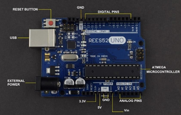
Know your components - Arduino Uno
Microcontroller |
ATmega328P – 8 bit AVR family microcontroller |
|---|---|
Operating Voltage |
5V |
Recommended Input Voltage |
7-12V |
Input Voltage Limits |
6-20V |
Analog Input Pins |
6 (A0 – A5) |
Digital I/O Pins |
14 (Out of which 6 provide PWM output) |
DC Current on I/O Pins |
40 mA |
DC Current on 3.3V Pin |
50 mA |
Flash Memory |
32 KB (0.5 KB is used for Bootloader) |
SRAM |
2 KB |
EEPROM |
1 KB |
Frequency (Clock Speed) |
16 MHz |
Pin Category |
Pin Name |
Details |
|---|---|---|
Power |
Vin, 3.3V, 5V, GND |
Vin: Input voltage to Arduino when using an external power source. 5V: Regulated power supply used to power microcontroller and other components on the board. 3.3V: 3.3V supply generated by on-board voltage regulator. Maximum current draw is 50mA. GND: ground pins. |
Reset |
Reset |
Resets the microcontroller. |
Analog Pins |
A0 – A5 |
Used to provide analog input in the range of 0-5V |
Input/output Pins |
Digital Pins 0 - 13 |
Can be used as input or output pins. |
Serial |
0 (Rx), 1(Tx) |
Used to receive and transmit TTL serial data. |
External Interrupts |
2, 3 |
To trigger an interrupt. |
PWM |
3, 5, 6, 9, 11 |
Provides 8-bit PWM output. |
SPI |
10 (SS), 11 (MOSI), 12 (MISO) and 13 (SCK) |
Used for SPI communication. |
Inbuilt LED |
13 |
To turn on the inbuilt LED. |
TWI |
A4 (SDA), A5 (SCA) |
Used for TWI communication. |
AREF |
AREF |
To provide reference voltage for input voltage. |
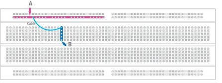
Know your components - Breadboard
A breadboard is a solderless device for temporary prototype with electronics and test circuit designs.
Most electronic components in electronic circuits can be interconnected by inserting their leads or terminals into the holes and then making connections through wires where appropriate.
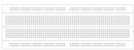
The breadboard has strips of metal underneath the board and connect the holes on the top of the board. The metal strips are laid out as shown below.
Note that the top and bottom rows of holes are connected horizontally and split in the middle while the remaining holes are connected vertically
Note how all holes in the selected row are connected together, so the holes in the selected column. The set of connected holes can be called a node:
To interconnect the selected row (node A) and column (node B) a cable going from any hole in the row to any hole in the column is needed:
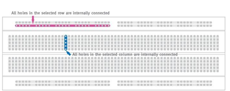
Now the selected column (node B) and row (node A) are interconnected
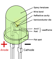
Know your components - LED
The “Light Emitting Diode” or LED as it is more commonly called, is basically just a specialized type of diode as they have very similar electrical characteristics to a PN junction diode.
This means that an LED will pass current in its forward direction but block the flow of current in the reverse direction. Flat Sport must be connected to GROUND
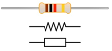
Know your components - Resistor
A resistor is a passive electrical component with the primary function to limit the flow of electric current
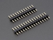
Know your components - Break Away Headers – Straight
Breakaway header is like the duct tape of electronics. Its great for connecting things together, soldering to perf-boards, fits into any breakout or breadboard,
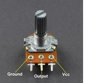
Know your components - 10K Potentiometer
You can connect VCC and GND on either first or third terminal of potentiometer. It is variable resistor which has no polarity. By default, GND Pin has 0Ω Value and VCC Pin has 10KΩ Value
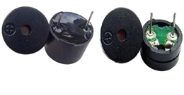
Know your components - Active VS Passive Buzzer
An active buzzer will generate a tone using an internal oscillator, so all that is needed is a DC voltage. A passive buzzer requires an AC signal to make a sound. It is like an electromagnetic speaker, where a changing input signal produces the sound, rather than producing a tone automatically.
Operating Voltage: 3.5-5.5V AC (Alternating current)
Rated Voltage: 5Vac
Current Consumption: 25mA
Resonant Frequency: 2300500Hz
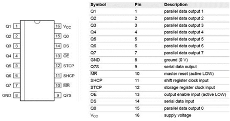
Know your components -HC595 shift Register
Wide Supply Voltage Range from 2.0V to 6.0V
Sinks or sources 8mA at VCC = 4.5V
CMOS low power consumption
Schmitt Trigger Action at All Inputs
Inputs accept up to 6.0V
ESD Protection Tested per JESD 22
Know your components - IR Sensor with HX1838 IR Remote
Remote Specifications:
Works on CR2025 button batteries, capacity : 160 mah
Working Distance: more than 8 m (effected by the surrounding environment, the receiver sensitivity, etc)
Effective Angle: 60 degrees
Surface materials: 0.125 mm PET stick
Effective button life: 20000 times.
Static current: 3-5 uA
Dynamic current: 3-5 mA
Infrared wavelength: 940Nm
Crystal: the oscillation frequency of 455 KHz
IR carrier frequency: 38KHz
Encoding: NEC encoding format
Infrared Receiver Specifications: An infrared receiver tuned to react only to IR of frequency 38 kHz. This IR sensor module consists of a PIN diode and a pre amplifier which are embedded into a single package. The output of TSOP is active low and it gives +5V in off state. When IR waves, from a source, with a center frequency of 38 kHz incident on it, its output goes low. It is perfect for making obstacle sensors and to accept signals from most IR remotes.
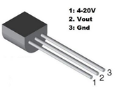
Know your components - LM35 Temperature Sensor
The LM35 is one kind of commonly used temperature sensor that can be used to measure temperature with an electrical o/p comparative to the temperature (in °C).
It can measure temperature more correctly compare with a thermistor.
This sensor generates a high output voltage than thermocouples and may not need that the output voltage is amplified.
The LM35 has an output voltage that is proportional to the Celsius temperature. The scale factor is .01V/°C.
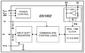
Know your components - DS1302 Real Time Clock
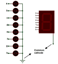
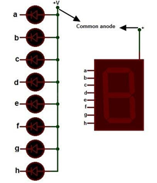
Know your components - 7 Segment Display
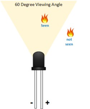
Know your components - Flame Sensor
Know your components - RGB Led

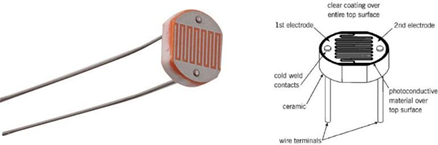
Know your components - LDR
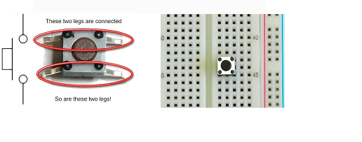
Know your components - Tactile Push Button Switch
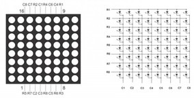
Know your components - 8*8 Dot Matrix Module
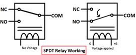
Know your components - 1 channel 5V relay Module
Know your components - DS1302 RTC Module
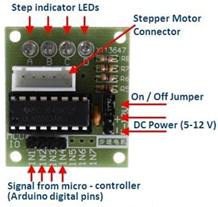
Know your components - ULN2003 Driver Module
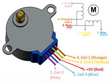
Know your components - 5V Stepper Motor
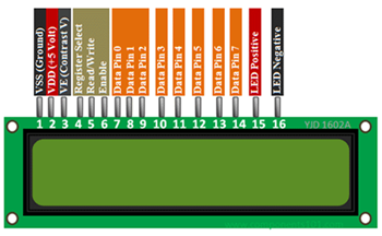
Know your components - 16x2 LCD
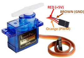
Know your components - Servo motor
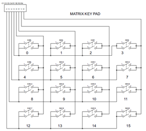
Know your components - Matrix keyboard module
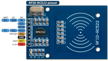
Know your components - RFID Card module
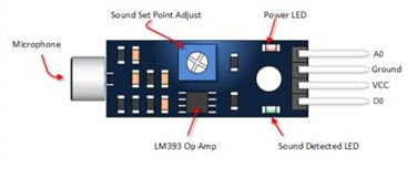
Know your components - Sound Sensor
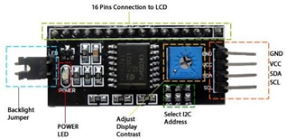
Know your components - I2C Display
LCD Display utilizes an I2C interface, which means that fewer pins are necessary to use this product than would be needed with a regular 16x2 LCD Display (just four connections, VCC, GND, SDA & SCL are required).
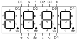
Know your components - 4 Digit (7 Segment) Display
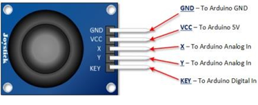
Know your components - Joystick Module
A joystick is an input device consisting of a stick that pivots on a base and reports its angle or direction to the device it is controlling. The Joystick Module is a tiny low cost option to add a game like control to your projects. The module has 2 potentiometers for the X and Y axis measurements. Also a switch that can give an additional control option
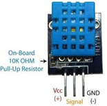
Know your components - DHT-11 Temperature Humidity Sensor
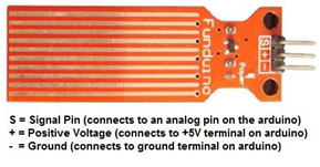
Know your components - Water Level Measurement Sensor
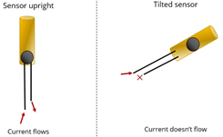
Know your components - Tilt Sensor
Tilt switches transfer a change-of-state to another device. These devices receive a signal from the tilt sensor for changes in motion or orientation and turn on or off. They do this by generating an artificial horizon and measuring angular tilt with respect to this horizon. Not all products open or close a switch. Such as tilt switch alarms, trigger audible or visual responses to notify an operator that a system is out of alignment