Program: PWM (Pulse Width Modulation)
Step 1: Read an analog input pin, map the result, and then use that data to dim or brighten an LED.
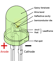
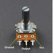
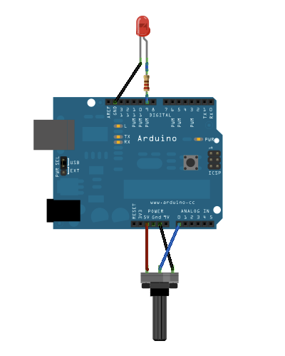
Step 2: Apparatus is arduino uno board, jumper wires (male to male), printer wire to connect board to PC and resistor, LED and potentiometer. See image below
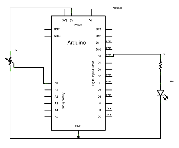
const int analogInPin = A0;  // Analog input pin that the potentiometer is attached to
const int analogOutPin = 9; // Analog output pin that the LED is attached to

int sensorValue = 0;        // value read from the pot
int outputValue = 0;        // value output to the PWM (analog out)

void setup() {
  // initialize serial communications at 9600 bps:
  Serial.begin(9600);
}

void loop() {
  // read the analog in value:
  sensorValue = analogRead(analogInPin);
  // map it to the range of the analog out:
  outputValue = map(sensorValue, 0, 1023, 0, 255);
  // change the analog out value:
  analogWrite(analogOutPin, outputValue);

  // print the results to the Serial Monitor:
  Serial.print("sensor = ");
  Serial.print(sensorValue);
  Serial.print("\t output = ");
  Serial.println(outputValue);

  // wait 2 milliseconds before the next loop for the analog-to-digital
  // converter to settle after the last reading:
  delay(2);
}
Program: PWM (Pulse Width Modulation)
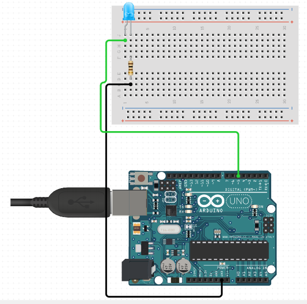
Step 1: Analog outputs are in range of 0 - 255 and can take any values from GND to VCC.
Step 2: Apparatus is arduino uno board, jumper wires (male to male), printer wire to connect board to PC and resistor and LED. See image below
const int LED_analog = 5;
void setup() {
    pinMode(LED_analog,OUTPUT);
}

void loop() {
    for (int brightness=1;brightness<=255;brightness++)
    {
      analogWrite(LED_analog,brightness);
      delay(10);
    }
    for (int brightness=255;brightness>0;brightness--)
    {
      analogWrite(LED_analog,brightness);
      delay(10);
    }
}
Program: Digital Input with Output
Step 1: Analog outputs are in range of 0 - 255 and can take any values from GND to VCC.
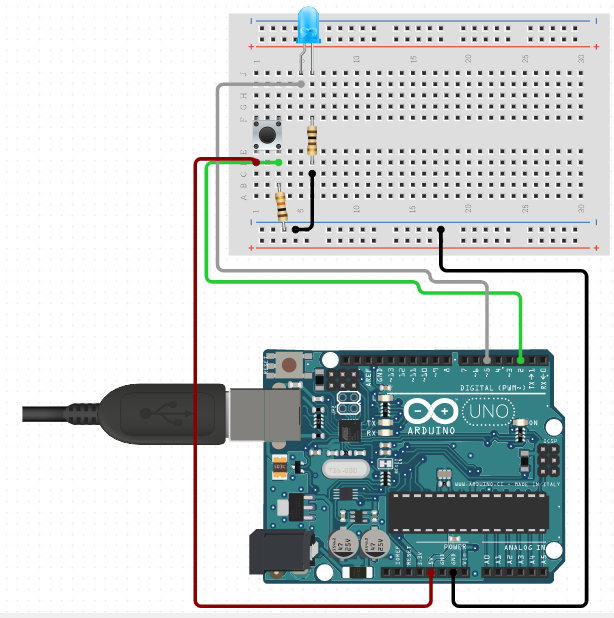
Step 2: Apparatus is arduino uno board, jumper wires (male to male), printer wire to connect board to PC, button, resistor and LED. See image below
const int BUTTON=2;
const int LED=5;
int BUTTONState=0;

void setup() {
  // put your setup code here, to run once:
pinMode(LED,OUTPUT);
pinMode(BUTTON,INPUT);
}

void loop() {
  // put your main code here, to run repeatedly:
BUTTONState = digitalRead(BUTTON);
if (BUTTONState == HIGH)
{
  digitalWrite(LED,HIGH);
}
else{
  digitalWrite(LED,LOW);
}
}
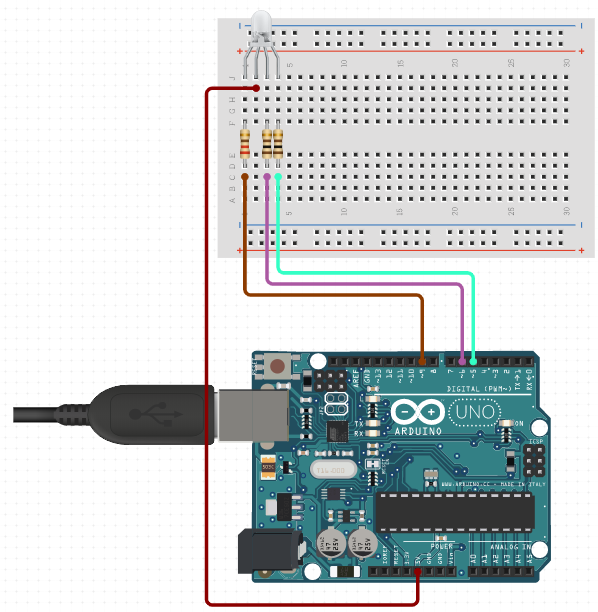
Program: RGB LED
RGB LED is a combination of 3 LEDs which are Red, Green and Blue. Red, green and blue can make any color.
By varying supplied voltages to RGB LEDs different colors are formed.
In arduino different voltages are supplied using analog out function.
RGB LED can be of two types: Common anode where anode (+) is common. Common cathode where cathode (-/GND) is common.

const int RED=5;
const int GREEN=6;
const int BLUE=9;

void setup()
{
  pinMode(RED,OUTPUT);
  pinMode(GREEN,OUTPUT);
  pinMode(BLUE,OUTPUT);
}
void loop()
{
  analogWrite(RED,100);
  analogWrite(GREEN,100);
  analogWrite(BLUE,100);
  delay(1000);
  analogWrite(RED,50);
  analogWrite(GREEN,50);
  analogWrite(BLUE,50);
  delay(1000);
}