Arduino sketch: Servo motor
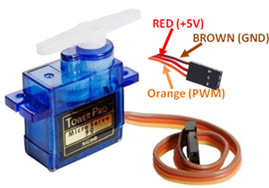
Step 1: An actuator that rotates to a precise angle through a command. The servo angle can rotate to any angle between 0 - 180. The servo receives command from the arduino moves to the commanded angle and stops there. The servo has three pin interface with power supply, ground and signal.
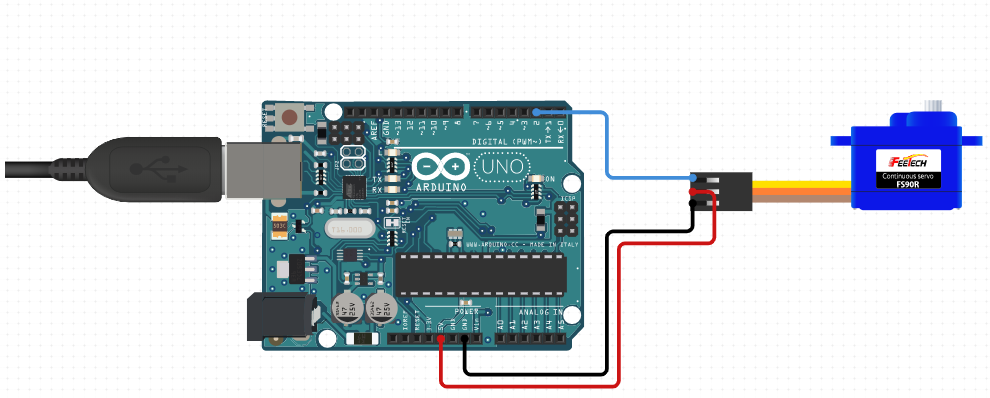
Step 2: Apparatus is arduino uno board, jumper wires (male to male), printer wire to connect board to PC and servo motor. See image below
#include <Servo.h>
Servo servo_1;

void setup()
{
\\attaches servo to pin 2.
  servo_1.attach(2);
}

void loop(){
  servo_1.write(45);
  delay(1000);
  servo_1.write(90);
  delay(1000);
}
Arduino sketch: Traffic Light
In this project we will make traffic lights using 3 LEDs with different color other than 1 LED and make them work accordingly
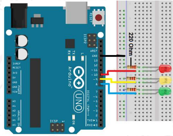
Hardware Required Breadboard 830 points - 1 Arduino Uno with USB Cable – 1 Single stand wire 2mt – 1 M5 LED (Red, Yellow, Green) – 2 pcs each 220Ω resistor – 5 Jumper wires (Male to Male) – 40 pcs
Circuit Connection Attach the three LEDs on the Breadboard. Connect GND of Arduino with the Breadboard for further GND Connections. Connect negative terminals of LEDs with the GND rail of the Breadboard via 220Ω resistor. Connect positive terminal of Red LED with the Digital Pin 10 of the Arduino Uno. Connect positive terminal of Yellow LED with the Digital Pin 9 of the Arduino Uno. Connect positive terminal of Green LED with the Digital Pin 8 of the Arduino Uno.
The green light will be on for 5 seconds, and then off., followed by the yellow light blinking for 3 times, and then the red light on for 5 seconds, forming a cycle. And the Cycle repeats.
int redled =10; // initialize digital pin 10.
int yellowled =9; // initialize digital pin 9.
int greenled =8; // initialize digital pin 8.

void setup()
{
pinMode(redled, OUTPUT);// set the pin with red LED as “output”
pinMode(yellowled, OUTPUT); // set the pin with yellow LED as “output”
pinMode(greenled, OUTPUT); // set the pin with green LED as “output”
}
void loop()
{
digitalWrite(greenled, HIGH);//// turn on green LED
delay(5000);// wait 5 seconds
digitalWrite(greenled, LOW); // turn off green LED
for(int i=0;i>3;i++)// blinks for 3 times
{
delay(500);// wait 0.5 second
digitalWrite(yellowled, HIGH);// turn on yellow LED
delay(500);// wait 0.5 second
digitalWrite(yellowled, LOW);// turn off yellow LED
}
delay(500);// wait 0.5 second
digitalWrite(redled, HIGH);// turn on red LED
delay(5000);// wait 5 second
digitalWrite(redled, LOW);// turn off red LED
}
Arduino sketch: LED in series
In this particular project, the LED’s blink by sequence in a series pattern
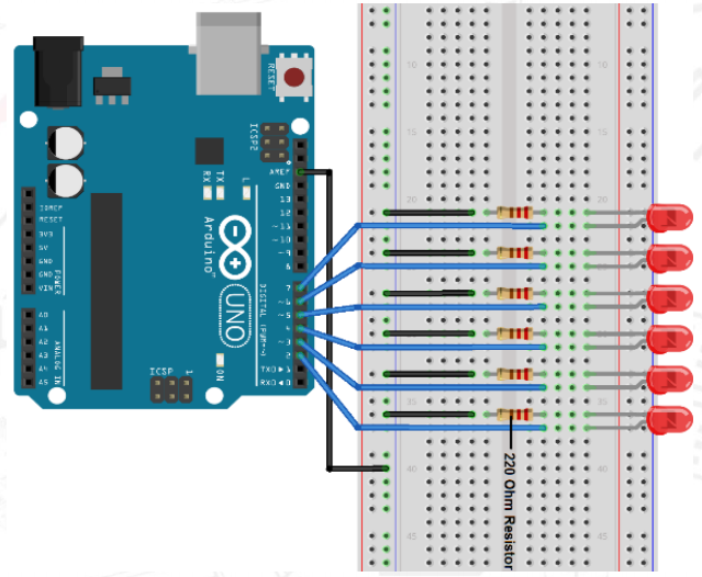
Hardware Required Jumper wires (Male to Male) – 40 pcs White LED – 3 220Ω resistor – 6 Arduino Uno with USB Cable – 1 Blue LED - 3 Breadboard 830 points – 1
Connections required: Attach the six LEDs on the Breadboard. Connect the GND of Arduino Uno with the Breadboard to make further GND connections. Connect negative terminals of all the LEDs with the GND rail of the Breadboard via 220Ω resistor. Connect the Positive terminals of all the LED with Arduino Uno as follows: LED Arduino Uno LED 1 -> Digital Pin 2 LED 2 -> Digital Pin 3 LED 3 -> Digital Pin 4 LED 4 -> Digital Pin 5 LED 5 -> Digital Pin 6
int BASE = 2 ;  // the I/O pin for the first LED
int NUM = 5;   // number of LEDs
void setup()
{
   for (int i = BASE; i < BASE + NUM; i ++)
   {
     pinMode(i, OUTPUT);   // set I/O pins as output
   }
}
void loop()
{
   for (int i = BASE; i < BASE + NUM; i ++)
   {
     digitalWrite(i, LOW);    // set I/O pins as “low”, turn off LEDs one by one
     delay(200);        // delay
   }
   for (int i = BASE; i < BASE + NUM; i ++)
   {
     digitalWrite(i, HIGH);
     delay(200);
   }
}
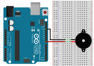
Arduino sketch: Active buzzer
Active buzzer is widely used on computer, printer, alarm, electronic toy, telephone, timer etc as a sound making element.
Hardware Required Jumper wires (Male to Male) – 40 pcs Active Buzzer - 1 Arduino Uno with USB Cable - 1 Breadboard 830 points - 1
Connections required: First, attach the active Buzzer on the Breadboard. Connect Digital Pin 8 of arduino Uno with positive terminal of active Buzzer. Connect GND of arduino Uno with negative terminal of Buzzer
When the circuit is finished, you can begin programming. Program is simple. You control the buzzer by outputting high/low level.
int buzzer=8;// initialize digital IO pin that controls the buzzer
void setup()
{
  pinMode(buzzer,OUTPUT);// set pin mode as “output”
}
void loop()
{
digitalWrite(buzzer, HIGH); // produce sound
}
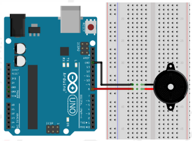
Arduino sketch: Passive buzzer
The buzzer we introduced here is a passive buzzer. It cannot be actuated by itself, but by external pulse frequencies. Different frequencies produce different sounds.
Hardware Required Breadboard 830 points - 1 Passive buzzer - 1 Arduino Uno with USB Cable - 1 Jumper wires (Male to Male) – 40 pcs
Connections required: First, attach the passive Buzzer on the Breadboard. Connect the Digital Pin 8 of Arduino Uno with the positive terminal of the passive Buzzer. Connect the GND of Arduino Uno with the negative terminal of the passive Buzzer.
The Passive Buzzer is the slightly shorter one, with the electronics exposed on the bottom. You have to send it an AC "sound signal" via the Arduino.
int buzzer=8;// select digital IO pin for the buzzer
void setup()
{
pinMode(buzzer,OUTPUT);// set digital IO pin pattern, OUTPUT to be output
}
void loop()
{
unsigned char i,j;//define variable
while(1)
{
  for(i=0;i<80;i++)// output a frequency sound
    {
      digitalWrite(buzzer,HIGH);// sound
      delay(1);//delay1ms
      digitalWrite(buzzer,LOW);//not sound
      delay(1);//ms delay
    }
  for(i=0;i<100;i++)// output a frequency sound
    {
      digitalWrite(buzzer,HIGH);// sound
      digitalWrite(buzzer,LOW);//not sound
      delay(2);//2ms delay
    }
}
}