Photo Resistor or LDR
In this Project, we will work on Photo resistor (Photovaristor) which includes the photoelectric effect of semiconductor. Photovaristor is commonly applied in the measurement of light and light control.
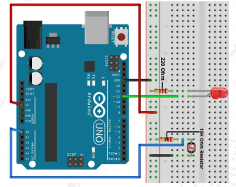
Hardware Required Arduino Uno with USB Cable - 1 Breadboard 830 points – 1 Photo resistor or LDR – 1 LED - 1 10KΩ resistor – 1 220Ω resistor – 1 Jumper wire (Male to Male) – 40 pcs
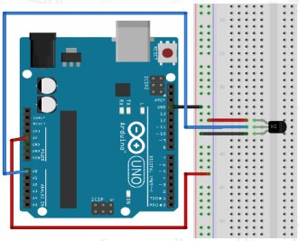
Circuit Connection Attach LED and LDR on the Breadboard. Connect GND of Arduino Uno with Breadboard to make further GND connections. Connect 5V Pin of Arduino Uno with Breadboard for further 5V power supply connections. Connect positive terminal of LED with the Digital Pin 11 of the Arduino Uno. Connect negative terminal of LED with the GND rail of Breadboard via 220Ω resistor. Connect the one leg of LDR with the 5V power supply rail of Breadboard via 10KΩ resistor on one end and connect other end with the Analog Pin A0 of Arduino Uno. Connect other leg of the LDR with the GND rail of Breadboard
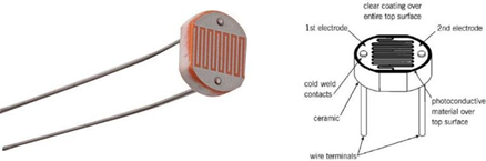
The photoelectric effect of semiconductor. Its basic working principle is that if the incident light is intense, its resistance reduces; if the incident light is weak, the resistance increases. Photovaristor is commonly applied in the measurement of light, light control and photovoltaic conversion (convert the change of light into the change of electricity).
Photo resistor is also being widely applied to various light control circuit, such as light control and adjustment, optical switches etc. Photovaristor is an element that changes its resistance as light strength changes.
So we will need to read the analog values. We can refer to the PWM experiment, replacing the potentiometer with photovaristor. When there is change in light strength, there will be corresponding change on the LED.
After the connection, let's begin the program compilation process. The program is similar to the one of PWM. After downloading the program, you can change the light strength around the photovaristor and see corresponding brightness change of the LED.
int potpin=0;// initialize analog pin 0, connected with photovaristor
int ledpin=11;// initialize digital pin 11, output regulating the brightness of LED
int val=0;// initialize variable val
void setup()
{
pinMode(ledpin,OUTPUT);// set digital pin 11 as “output”
Serial.begin(9600);// set baud rate at “9600”
}
void loop()
{
val=analogRead(potpin);
Serial.println(val);
analogWrite(ledpin,val);
delay(10);
Detect Flame using Flame Sensor
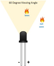
Flame sensor (Infrared receiving triode) is specially used on robots to find the fire source. This sensor is of high sensitivity to flame.
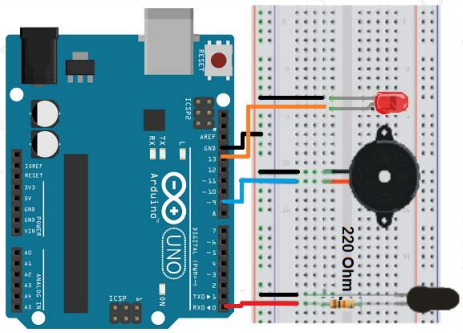
Hardware Required Arduino Uno with USB Cable – 1 B10 Buzzer – 1 Flame Sensor – 1 LED - 2 Breadboard 830 points – 1 Jumper Wire (Male to Male) – 40 pcs 220Ω resistor – 2
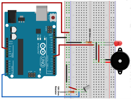
Circuit Connection Connect GND of Arduino Uno with Breadboard for further GND connections. Attach Buzzer, LED and flame sensor on the Breadboard. Connect the positive terminal of Buzzer with the Digital Pin 9 of the Arduino Uno. Connect negative terminal of LED, Flame sensor and Buzzer with the GND rail of the Breadboard. Connect positive terminal of Flame sensor with Digital Pin 0 of Arduino Uno via 220Ω resistor. Connect positive terminal of LED with Digital Pin 13 of Arduino Uno.
Flame sensor is made based on the principle that infrared ray is highly sensitive to flame. It has a specially designed infrared receiving tube to detect fire, and then convert the flame brightness to fluctuating level signal. The signals are then input into the central processor and be dealt with accordingly.
When it's approaching a fire, the voltage value the analog port reads differs. If you use a multi meter, you can know when there is no fire approaching, the voltage it reads is around 0.3V; when there is fire approaching, the voltage it reads is around 1.0V, the nearer the fire, the higher the voltage. So in the beginning of the program, you can initialize voltage value i (no fire value);
Then, continuously read the analog voltage value j and obtain difference value k=j-i; compare k with 0.6V (123 in binary) to determine whether or not there is a fire approaching; if yes, the buzzer will buzz.
int flame=0;// select digital pin 0 for the sensor
int Beep=9;// select digital pin 9 for the buzzer
int val=0;// initialize variable
int led= 13; // Select Digital Pin 13 for the LED
void setup()
{
 pinMode(Beep,OUTPUT);// set buzzer pin as “output”
 pinMode(led,OUTPUT);// set LED pin as “output”
 pinMode(flame,INPUT);// set flame pin as “input”
 Serial.begin(9600);// set baud rate at “9600”
}
void loop()
{
 val=analogRead(flame);// read the analog value of the sensor
 Serial.println(val);// output and display the analog value
 if(val>=300)// when the analog value is larger than 300, the buzzer will buzz
 {
 digitalWrite(Beep,HIGH);
 digitalWrite(led,HIGH);
 }
else
 {
 digitalWrite(Beep,LOW);
 digitalWrite(led,LOW);
 }
 delay(500);
}
Basic LM35 Temperature Sensor
LM35 is a common and easy-to-use temperature sensor. It does not require other hardware. You just need an analog port to make it work but difficulty lies in compiling code to convert analog value it reads to Celsius temperature
Hardware Required Arduino Uno with USB Cable - 1 Breadboard 830 points – 1 Jumper wires (Male to Male) – 40 pcs LM35 Temperature Sensor Module – 1
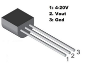
Circuit Connection Attach the LM35 Temperature Sensor with the Breadboard. Connect the GND of Arduino Uno with Breadboard for making further GND connections. Connect Pin 5V of Arduino Uno with Breadboard for making further 5V power supply connections. Connect GND of LM35 Temperature Sensor with GND rail of Breadboard. Connect VCC of LM35 Temperature Sensor with 5V power supply rail of Breadboard. Connect Signal Pin of LM35 Temperature Sensor with Analog Pin A0 of Arduino Uno.
The LM35 series are precision integrated-circuit temperature devices with an output voltage linearly-proportional to the Centigrade temperature. The LM35 sensor does not require any external calibration or trimming to provide typical accuracies of ±¼°C at room temperature and ±¾°C over a full −55°C to 150°C temperature range. The LM35 is one kind of commonly used temperature sensor that can be used to measure temperature with an electrical o/p comparative to the temperature (in °C). It can measure temperature more correctly compare with a thermistor. This sensor generates a high output voltage than thermocouples and may not need that the output voltage is amplified. The LM35 has an output voltage that is proportional to the Celsius temperature. The scale factor is .01V/°C.
Lm35 voltage conversion to temperature formula/equation derivation for Arduino Arduino analog pins can measure up-to +5 volts OR the voltage on which it is working normally +5 volts. Arduino analog pin resolution is 1023 starting from 0. On +5 volts input it counts to 1023. Lm35 max voltage output is 1500mV( At 150 degree centigrade). 1500mV is equal to 1500/1000 = 1.5 volts. So Lm35 at max outputs 1.5 voltage. Arduino analog pin count for 1.5 volts equals to (1.5 / 5)*1023 = 307.5 . At +5 volts its 1023 and at 1.5 volts its 307.5. New Arduino-Lm35 Resolution = 307.5 / 150 = 2.048 . Now if arduino analog pin counts 2.048 its equal to 1 degree change in centigrade/Celsius temperature of LM35.
int potPin = 0; // initialize analog pin 0 for LM35 temperature sensor
void setup()
{
Serial.begin(9600);// set baud rate at”9600”
}
void loop()
{
int val;// define variable
val=analogRead(potPin);
float temperatureC=val/2.048;
Serial.print("Temp:");// output and display characters beginning with Tep
Serial.print(temperatureC);// output and display value of dat
Serial.println("C");// display “C” characters
delay(500);// wait for 0.5 second
}
Tilt Switch
Tilt switches are used for controlling various types of Modules. But here we will be controlling an LED and Turn it ON/OFF respectively. Also, we will be using buzzer as an additional feature of the circuit.
Hardware Required Arduino Uno with USB Cable – 1 Tilt Switch – 1 Blue LED – 2 220Ω resistor – 2 10KΩ resistor - 2 Breadboard 830 points – 1 Jumper wire (Male to Male) – 40 pcs B-10 Passive Buzzer - 1
Circuit Connection Attach LED and Buzzer on the Breadboard. Connect GND of Arduino Uno with Breadboard for further GND connections. Connect Pin 5V of Arduino Uno with Breadboard for further 5V power supply connections. Connect positive terminal of LED and Buzzer with Digital Pin 7 of Arduino Uno. Connect negative terminal of LED and Buzzer with GND rail of Breadboard via 220Ω resistor. Attach Tilt switch on the Breadboard. Connect one terminal of Tilt switch with 5V power supply rail of the Breadboard. Connect other terminal of Tilt switch with Analog Pin A5 of Arduino Uno via 10KΩ resistor
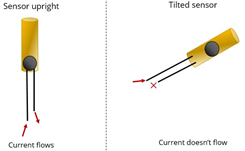
When one end of the switch is below horizontal position, the switch is on. The voltage of the analog port is about 5V (1023 in binary). The LED will be on. When the other end of the switch is below horizontal position, the switch is off. The voltage of the analog port is about 0V (0 in binary). The LED will be off. In the program, we determine whether the switch is on or off according to the voltage value of the analog port, whether it's above 2.5V (512 in binary) or not.
 void setup()
{
  pinMode(7,OUTPUT);// set digital pin 7 as “output”
}
void loop()
{
int i;// define variable i
while(1)
{
  i=analogRead(5);// read the voltage value of analog pin 5
  if(i>512)// if larger that 512(2.5V)
  {
    digitalWrite(7,LOW);// turn on LED
  }
  else// otherwise
  {
    digitalWrite(7,HIGH);// turn off LED
  }
 }
}
Control inbuilt LED using Serial monitor
Hardware Required Arduino Uno with USB Cable – 1
Circuit Connection Connect arduino uno with PC using printer wire.
Serial.available() Gets the number of bytes (characters) available for reading from the serial port. If user gives input, then bytes available are more than zero. Then Serial.read() is used to get input from serial monitor. This is given to if else logic
void setup()
{
pinMode(13,OUTPUT);
Serial.begin(9600);
}
void loop()
{
if(Serial.available() > 0)
{
char data = Serial.read();
if(data == '0')
{
digitalWrite(13,HIGH);
}
else if (data == '1')
{
digitalWrite(13,LOW);
}
}
}