Debugging
Debugging is after you write your code and you try to run it and it doesn't work, trying to fix the code.
With these IOT devices, there's a software part, but there's also the hardware part. And, you have to debug them both together, which adds complexity.
Given the code, how do you debug that code?
Debug and Trace - one thing about debugging and testing in general in debugging is that you require controllability and observability to locate the bug.
Controllability is the ability to control sources of data that are used by the system. The input pins are the sources of data for a microcontroller. The input pins receive data from sensors and hence controlling the environment allows you to control the sensor and in turn decide what input the pin is receiving.
For example, changing the room temperature you can control the input the arduino receives via the temperature sensor.
In addition to that, you would optimally like to be able to control the internal data, meaning the storage elements, the registers and the memory inside the chip.
Controllability allows you to do testing to test certain circumstances that you think might be causing a bug or triggering a bug at any rate. So addition to controllability you need observability.
Observability is the ability to observe intermediate and final results.
First thing you need to observe are the output pins. The outputs of the whole system, you need to see what values are on those pins. Now often you can observe these directly through the actuators.
So say the output pin is connected to an LED. You look at the LED, you can tell if the pen is high or low.
You can also directly observe the pins If you take a multimeter and wire it straight to the pins.
Now again, you would also optimally like to be able to observe the registry content. So you'd be able to, like to be able to look at the registry values at a certain point in time, see what they are.
So you need controllability and observabilitysomehow in order to do testing and do debugging.
Properties of debugging environment.
Run control of the target - be able to stop and start the program in the middle. Generally this is done using breakpoints.
Real-time monitoring of the target - The timing execution of the target. You view data about the execution in real time right. As it is executing, you are viewing the data. So for instance, say there's a value x of variable x, you don't have to stop the program and then say print x. You can just see x coming out on some pins while it's executing. Without slowing down the processor, you can still see the value of x, let's say.
Timing and functional accuracy - You want the IOT version to be exactly the same in terms of timing as the planned and you want functional accuracy which means the behavior of the system is also as planned.
Debugging Environments
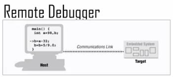
Remote debugger: there are basically two components is a host. Host computer and target. The target is the target platform that we're dealing with. In our case that would be the Arduino or whatever whatever board we want to work with. The host computer is where you as a user, as a programmer. Actually interface with the debugging environment. You are using the typing debug commands into the host. Those are getting transmitted to the target over some kind of communication link.
The frontend is running on the host that you, the programmer, are accessing. Debug monitor code that's running on the platform typically triggered when some debug event occurs. If you set a break point on line 23 so when line 23 happens, the target stops. It recognizes the debug event and it stops running.
Then it goes back to the host and lets the host have control again.
Debug Monitor: the code running on the target that's talking to the host.
So for instance, if the host types print the contents of variable X. That command will be sent over the communication interface and then the debug monitor will receive it. It will retrieve the value of x and send it back over the communication link. So the host front-end is actually talking to this debug monitor.
Disadvantage of this is you need a spare communication channel, so the host and the target are speaking over some communication channel. So you need an extra communication channel, one that's not being used functionally.
Embedded debug interface : inside the processor or the microcontroller, in addition to all the logic that actually executes the code. They put debug logic hardware that actually does debug activities. They build it right in, so you don't have to have a debug monitor anymore.
Debug via serial
Observability - observing information about what's going on when you're running the Arduino, when you're running the code. One way is to just look at the output pins, but we often wanna see more important, more detailed informationt.
And so, we need some way to transfer information from the Arduino, or some microcontroller, to the host that we're debugging from. And serial interface is how its done.
Serial protocols is where you transmit data serially. You transmit data one bit at a time, or one chunk at a time. In Arduino uno's case, one bit at a time.
The Arduino uno microprocessor AT Mega 328 is a eight bit processor
So the parallel data generated by the microprocessor are to be transmitted one bit at a time. The reason why we do this, is because it saves us pins. At the receiving end they are to be received one at a time but grouped back into eight bits
So they receive one at a time, and once you get to eight that's a byte, and it sends it off and processes it. So we do this to save pins.
Serial protocols are slower because instead of sending all eight pins in one clock cycle you have to send one at a time. So it slows you down but it saves pins and pins are important.
A popular serial protocol is UART. UART stands for Universal Asynchronous Receiver/Transmitter.
It's asynchronous, meaning no shared clock. A clock is basically a square wave. And the square wave has rising edges and falling edges. And all the devices in the system time themselves off of the rising edge. One goal when you're using a clock is that every item that's receiving the clock, they have to receive the rising edge at the same time. This is a major problem.
Example, a mother board of a computer has a system clock. The system clock goes to all the parts that receive all the chips on the mother board. And the system clock is run at a certain frequency. And the rising edge has to travel from wherever the clock is generated, to the chip. And there is a certain amount of distance.
It is important that the rising edge arrives at every destination at the same time, or very close to it. That's the assumption for all of our systems, that all the parts on your device that are receiving the clock, they all receive the rising edge at the same time. Now that's hard to guarantee in any kind of a big system because every distance takes a certain amount of time to travel.
And that makes UART a nice thing, because UART is asynchronous meaning it doesn't have a clock. Now as a result of that, UART is slower than a lot of other protocols. But it has that advantage that it can work over very long distances because it doesn't require them to have the same clock.
UART protocol
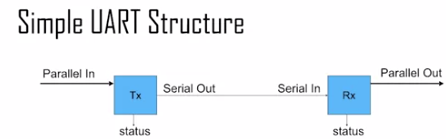
You've got two sides to the communication. The sender, the transmitter and the receiver. The transmitter is Tx. The receiver is Rx, and you can see in between the transmitter and the receiver, there is a serial a single wire.
Now generally, there might be two but there might be a ground but let's say a single wire. Serial out of the transmitter. Serial into the receiver.
If we look at the transmitter side, you've got parallel data coming in on the left. So that typically would be a byte or some chunk of data. So let's say it's 8 bits, an 8 bit byte. So 8 bits comes in. The transmitter sends those bits on serial out.
The bits get received by the receiver on serial in and then it creates parallel data and sends that back out on parallel out to the rest of the system.
So the data is serialized by Tx. What that means is say 8 bits come in on parallel in, they get serialized. Set one at a time, one bit at a time on serial out. And then they deserialize them on the receiving end. So they come in one bit at a time and then they get packaged into chunks of probably 8 bits.
The status data, there's a status of the Tx and the Rx on both sides. The status is usually indicating the state of the transmit and receive buffers. So what that means is inside Tx and Rx, inside the transmitter and receiver you've typically got buffers.
So for instance on the receiving end, you're probably gonna have some receiving buffer. So you'll be receiving one bit at a time and filling up a buffer, and once a buffer is full and you can send it out on parallel out to the rest of the system.
So when these buffers are full, you can't receive anymore. So the receiver can't receive if the buffer's full. Also the sender can't send if its buffer is empty. Since there is no data to send.
So the status bits are basically information about that that goes back to the code running on the transmitter and receiver to tell it if you should be able to send a new piece of data or receive a new piece of data and so forth.
Flow control: the receiver is receiving data at the same rate that the transmitter is transmitting it. If the receiver is receiving data faster than the transmitter then the transmitter can't keep up and the receiver will be stopped.
And vice versa, if the receiver is receiving data slower then the transmitter will be too fast and it'll have to stop. So you wanna match those rates, so that you don't lose any data.
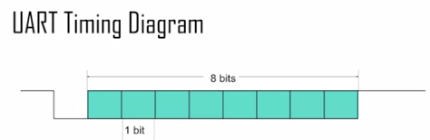
UART timing diagram : This timing diagram given below is showing you is, it's showing you the value on that serial wire between the transmitter and the receiver.
So let's break this down, this communication. So this is an example of sending one byte of data via UART. So the first bit is the start bit and that initiates the transfer. Start bit starts off high by default but as soon as you wanna start sending some data it goes low.
Now after that, the next bits are the data. So all those 8 bits that are green, those are data and those can be high or low. They're green and we don't draw them as high or low, they can be either, high or low.
After the 8 data bits are sent. Then the last 2 bits are the stop bits. And those tell the receiver okay, I'm done sending now.
So each bit that's being sent has a certain duration. It's sent on the wires for a certain period of time. Each bit transmitted for a fixed duration. This duration has to be known by both the transmitter and the receiver. So before you can do serial communication both the transmitter and the receiver have to know every bit is going to be either high or low for a certain fixed period of time.
The baud rate determines this fixed duration. So the duration we'll call T, it's the period. T is the common letter people use for the period. So the duration is T, the duration of a single bit. Tha baud rate is the frequency. It's the inverse of T. So baud rate is the number of transitions per second or the maximum number of transitions per second. And it's typically measured in bits per second because you can send one bit in every transition. T the period equals 1 over f. So if you know the baud rate, you invert that and that give you the period.
So for instance, common baud rate is 9600 , if you invert that to 1 over 9600 is approximately 104 microseconds.
The transmission rate is actually less than the baud rate. So the baud rate is the rate at which you're sending these bits. But remember that in addition to sending the data bits, you're sending this padding there are other bits that you send.
The start bit, that's a bit that you have to send but just to initiate the transfer. But it's not actually containing real data. So that's something of a waste. It's an overhead put it like that. It's not a waste you need it but it's an overhead. It's a bit of time that you send but you can't send real data. Also stop bits. Say, you're using two stop bits at the end.
Those are two more bits that are not sending data. So after the data transmission rate is actually less than the baud rate. Because there are start bits, stop bits and also other overhead.
So there are extra bits that you're sending. But the baud rate is the maximum data transmission rate but you can't actually achieve that. You need start bits, stop bits and parity bit
UART - Universal Asynchronous Receiver/Transmitter
The transmitter and the receiver have to be synchronized. That is the receiver has to know when to expect data from the transmitter.
And it has to be fairly accurate about the timing that it expects. And UART is an asynchronous protocol meaning it has no clock. Normally, if you have a synchronous protocol, the clock is how it's synchronized. When it sees the rising edge, it knows data will be sent. But this doesn't have a clock. So it has to figure out when data is gonna be sent another way.
UART synchronization : The receiver has to know when it's looking at that value on that wire, that serial wire. It also has to know which bit it's reading. If it's not synchronized properly then the receiver will not expect the bits at the right time. It'll receive the wrong data.
So the start bit is how synchronization happens. So the start bit remember, at the beginning before you've actually started sending anything, the wire is high. The single wire is gonna be high. The receiver knows its transmission is gonna start. The start bit is happening when it goes from high to low. So when there's a falling edge on that signal then it says okay, this is the start bit. Now is when I have to start synchronizing myself.
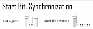
If some kind of electromagnetic noise forces the signal to go low, mistakenly. Receiver should ignore a short glitch. So what happens is, it's gonna measure the time that the signal is low.
So on the left, it's just a glitch. The signal goes low but for a very short time. If it's too short then the receiver should say oh, that's not real, that's not really a start.
But on the other hand on the right, if this signal goes low and stays low for a significant amount of time then the receiver should say oh, this is a real start I need to synchronize myself.
In the diagrams, those little up arrows on the timing diagrams are the sampling points. Those are the points in time where the receiver is checking the signal value. And you'll notice with the glitch, it goes low for only three sample sample points. That's not enough.
Where if you look at the one where the startup is detected, the one on the right, it's low for more sample points and it would say okay, that's efficient. So that's what's gonna happen on the receiver end.
It's gonna sample over and over, faster than the baud rate. Typically 16 times faster at least, and it's gonna count how many times to find the start bit, it's gonna count how many samples it's low for. If it's low for enough samples then it says yes, that is a real start.
So detection of the start bit is used to synchronize the receiver and the transmitter and it's synchronized based on the falling edge of the signal and it recognizes the start bit based on the falling edge.
UART - Universal Asynchronous Receiver/Transmitter (Parity bit)
In addition to the data bits and the start bit, you can transmit a Parity Bit. This is an optional bit that you can transmit with the data.
So transmission is assumed to be error prone. This is very common, long distance communication. You can have lots of electromagnetic radiation.
So this maybe synchronization accuracy, or inaccuracy, something like that. There are lots of reasons why there can be noise on a line. So there can be times where you expect a zero. Zero is being transmitted, but the receiver receives a one instead, or vice versa. You transmit a one but the receiver receives a zero, because of various types of noise.
So to adjust for that, to take care of that, at least to detect that, we have parity bits. So parity bit is optional. One parity bit can be sent with each packet, each, say group of eight data bits. The parity bit is used to check for error.
So let's say we're sending eight bits, eight data bits. The parity is the count, you either have even parity or odd parity, and it's related to the number of ones that are transmitted.
So, if you're transmitting eight bits and an odd number of those bits are ones, then you say you have odd parody. And if an even number of those bits is a one, then you have even parity.
Let's say even is zero and odd's a one. So parities of any sequence of bits is always even or odd depending on how many bits you're transmitting. So what we do is, if we use a parity bit, we send the data bits, and then we also send one more bit which is the parity bit, which is either zero or one. A zero if the parity of the other bits is even, a one if it's odd.
And then what can happen is on the receiving end, it can check the parity. So it can count the number of ones that it received, and checks if it's even or odd, and then it compares that to the parity bit. If the parity bit set is even, it's parity bit is zero, let's say, indicating that it's even parity, and it has an even number of ones, then it assumes, okay, transmission was fine.
Where if it gets odd parity, then it assumes that transmission was not fine, and it needs a new transmission. It basically sends some kind of request to say, send me the data again.
The parity bit is sent after the data bit. So you have the start bit, then you have the data bits, then you send the parity bit, then you send the stop bit, or bits. You can send one or more stop.
So if a single bit is changed, then this can be detected using a parity bit.
Data Throughput versus Baud: the Baud rate is the maximum number of transitions in a second. The maximum transitions, which is the maximum bits that you can send. And it's true that you can send that many bits, but not all of those bits are actually data bits. So the data throughput is not as high as the Baud rate,
Because you're sending the stop bit, the start bit and the parody bit. Stop bit could be two bits and the parity bit, you send extra stuff that is not actually data. So the data transmission rate is going to be less than the baud rate.
You're sending 11 bits a second, 8 data bits. So your data throughput, would be less because the transmission efficiency is only eight out of 11. So you get 73% efficiency out of that. So the data throughput rate is actually only 73% of 9600. So you get, 6981 bits per second of data that you can actually send when you're using 9600 baud under those assumptions.