Alarm System using DHT11 Humidity/Temp Sensor
The DHT11 Humidity/Temperature Sensor Module is used here.
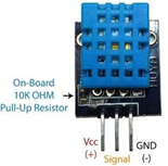
Working and Output Welcome to the Arduino Based Project which consists of DHT11 Humidity & Temperature Sensor. The DHT11 measures relative humidity. Relative humidity is the amount of water vapor in air vs. the saturation point of water vapor in air. At the saturation point, water vapor starts to condense and accumulate on surfaces forming dew.
The saturation point changes with air temperature. Cold air can hold less water vapor before it becomes saturated, and hot air can hold more water vapor before it becomes saturated. The formula to calculate relative humidity is: Relative humidity is expressed as a percentage.
At 100% RH, condensation occurs, and at 0% RH, the air is completely dry. First, we will display the values of Temperature and Humidity on the Serial Monitor.
#include <dht11.h>
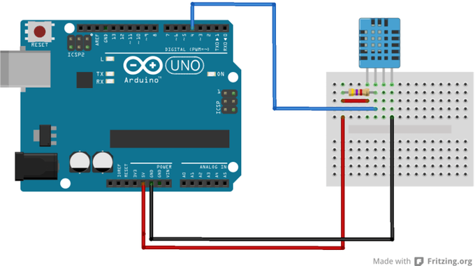
const int DHT11PIN = 4;
dht11 DHT11;
void setup()
{
Serial.begin(9600);
pinMode(DHT11,INPUT);
}
void loop()
{
Serial.println();
int chk = DHT11.read(DHT11PIN);
Serial.print("Humidity (%): ");
Serial.println((float)DHT11.humidity, 2);
Serial.print("Temperature (C): ");
Serial.println((float)DHT11.temperature, 2);
delay(2000);
}
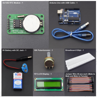
Display Date and Time on LCD using RTC1302 Module
In this project, we will display the current date and time on LCD using RTC1302 Module.
// Timur Maksiomv 2014
//
// A quick demo of how to use DS1302-library to make a quick
// clock using a DS1302 and a 16x2 LCD.


// DS1302:  CE pin    -> Arduino Digital 27
//          I/O pin   -> Arduino Digital 29
//          SCLK pin  -> Arduino Digital 31
//          VCC pin   -> Arduino Digital 33
//          GND pin   -> Arduino Digital 35
//
// LCD:     DB7       -> Arduino Digital 7
//          DB6       -> Arduino Digital 6
//          DB5       -> Arduino Digital 5
//          DB4       -> Arduino Digital 4
//          E         -> Arduino Digital 9
//          RS        -> Arduino Digital 8

#include <LiquidCrystal.h>
#include <DS1302RTC.h>
#include <Time.h>

// Init the DS1302
// Set pins:  CE, IO,CLK
DS1302RTC RTC(27, 29, 31);

// Optional connection for RTC module
#define DS1302_GND_PIN 33
#define DS1302_VCC_PIN 35

// Init the LCD
//   initialize the library with the numbers of the interface pins
//            lcd(RS,  E, d4, d5, d6, d7)
LiquidCrystal lcd(8,   9,  4,  5,  6,  7);

void setup()
{
  // Setup LCD to 16x2 characters
  lcd.begin(16, 2);

  // Activate RTC module
  digitalWrite(DS1302_GND_PIN, LOW);
  pinMode(DS1302_GND_PIN, OUTPUT);

  digitalWrite(DS1302_VCC_PIN, HIGH);
  pinMode(DS1302_VCC_PIN, OUTPUT);

  lcd.print("RTC activated");

  delay(500);

  // Check clock oscillation
  lcd.clear();
  if (RTC.haltRTC())
    lcd.print("Clock stopped!");
  else
    lcd.print("Clock working.");

  // Check write-protection
  lcd.setCursor(0,1);
  if (RTC.writeEN())
    lcd.print("Write allowed.");
  else
    lcd.print("Write protected.");

  delay ( 2000 );

  // Setup Time library
  lcd.clear();
  lcd.print("RTC Sync");
  setSyncProvider(RTC.get); // the function to get the time from the RTC
  if(timeStatus() == timeSet)
    lcd.print(" Ok!");
  else
    lcd.print(" FAIL!");

  delay ( 2000 );

  lcd.clear();
}

void loop()
{

  // Display time centered on the upper line
  lcd.setCursor(3, 0);
  print2digits(hour());
  lcd.print("  ");
  print2digits(minute());
  lcd.print("  ");
  print2digits(second());

  // Display abbreviated Day-of-Week in the lower left corner
  lcd.setCursor(0, 1);
  lcd.print(dayShortStr(weekday()));

  // Display date in the lower right corner
  lcd.setCursor(5, 1);
  lcd.print(" ");
  print2digits(day());
  lcd.print("/");
  print2digits(month());
  lcd.print("/");
  lcd.print(year());

  // Warning!
  if(timeStatus() != timeSet) {
    lcd.setCursor(0, 1);
    lcd.print(F("RTC ERROR: SYNC!"));
  }

  delay ( 1000 ); // Wait approx 1 sec
}

void print2digits(int number) {
  // Output leading zero
  if (number >= 0 && number < 10) {
    lcd.write('0');
  }
  lcd.print(number);
}
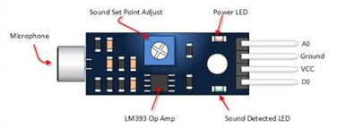
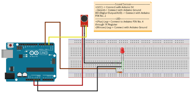
Make a Clap controlled LED using Sound Sensor
In this project, we will make a clap controlled LED using Sound Sensor which will turn the LED ON, on detecting High sound and turn OFF, on Low/No sound.
int soundSensor=2;
int LED=4;
boolean LEDStatus=false;

void setup() {
 pinMode(soundSensor,INPUT);
 pinMode(LED,OUTPUT);

}

void loop() {

  int SensorData=digitalRead(soundSensor);
  if(SensorData==1){

    if(LEDStatus==false){
        LEDStatus=true;
        digitalWrite(LED,HIGH);
    }
    else{
        LEDStatus=false;
        digitalWrite(LED,LOW);
    }
  }
 }
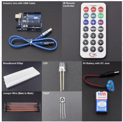
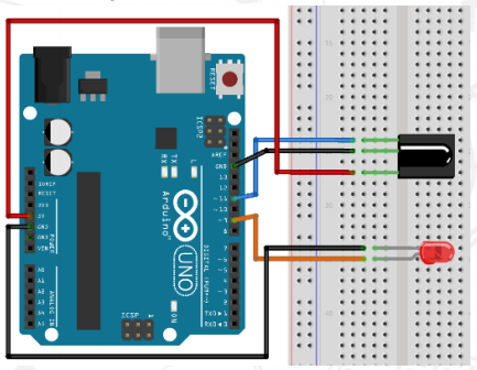
Control Brightness of LED using IR Sensor and IR Remote Controller
We will be controlling the Brightness of LED using IR Sensor and IR Remote Controller. This is the basic project to control intensity of LED
#include <IRremote.h> // use the library for IR
const int receiver = 11; // pin 1 of IR receiver to Arduino digital pin 11
const int ledPin =  9;
int fadeValue;
int lastCounter = 1;
int counter;
IRrecv irrecv(receiver); // create instance of 'irrecv'
decode_results results;

void setup()

{
  Serial.begin(9600);
  pinMode(ledPin, OUTPUT);
  irrecv.enableIRIn();
}

void loop()
{
  if (irrecv.decode(&results))
  {
    Serial.println(results.value, HEX);
  }
  counter = lastCounter;
  if (irrecv.decode(&results))
  {
    if (results.value == 0xFFA857)
    {
    counter ++;
    }
    if (results.value == 0xFFE01F)
    {
    counter --;
    }
  irrecv.resume();
  }
   if (counter > 5){    //maximum for counter = 5
    counter = 5;
  }
  if (counter < 2){ //minimum for counter = 1
    counter = 1;
  }

  switch (counter)  //depending on the counter the fadevalue is sent to the led
   {
  case 1:
  fadeValue = 00;
  break;

  case 2:
  fadeValue = 50;
  break;

  case 3:
  fadeValue = 120;
  break;

  case 4:
  fadeValue = 185;
  break;

  case 5:
  fadeValue = 255;
  break;
  }
  analogWrite(ledPin , fadeValue);  //set led with PWM value
  lastCounter=counter;
}